P/N 960-000173R_Rev. A {EDP #229278} © 2013, JAPAN CASH MACHINE CO., LTD.
EBA
®
Series
Banknote Acceptor (EBA-40)
List of Figures
Page
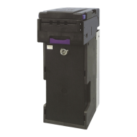
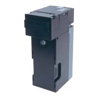
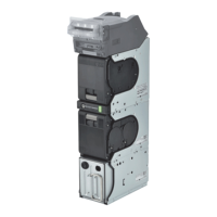
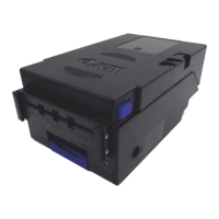
Figure 1 EBA-40 Unit ...............................................................................................1
Figure 2 Precautionary Symbols ..............................................................................2
Figure 3 Unacceptable Banknotes ...........................................................................4
Figure 4 Automatic Centering Mechanism (with the SD3 Stacker) ..........................4
Figure 5 Automatic Centering Mechanism (without the SD3 Stacker) .....................4
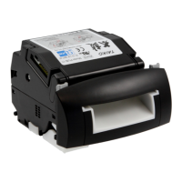
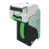
Figure 6 EBA-40 Component Names ......................................................................5
Figure 7 M3 Screw Locations (Bottom) ....................................................................8
Figure 8 Key Hole Slot Locations (Rear) .................................................................8
Figure 9 M4 Screw Locations (Rear & Bottom) .......................................................8
Figure 10 M3 Screw Locations (Rear & Bottom) .......................................................9
Figure 11 Key Hole Location ......................................................................................9
Figure 12 Lock Dimension & Cylinder Length ............................................................9
Figure 13 Key Unlock Rotation Requirement ...........................................................10
Figure 14 Retrieving Banknotes ...............................................................................18
Figure 15 Clearing an Entrance Banknote Jam .......................................................18
Figure 16 Clearing a Stacker Box Banknote Jam ....................................................18
Figure 17 Sensor Cleaning ......................................................................................19
Figure 18 EBA-40 Sensor and Roller Cleaning Locations .......................................19
Figure 19 EBA-40 TTL Interface Schematic Diagram ..............................................20
Figure 20 EBA-40 MDB Interface Schematic Diagram ............................................20
Figure 21 EBA-40 ccTalk Interface Schematic Diagram ..........................................21
Figure 22 EBA-40 Photo-Coupler Interface Schematic Diagram .............................21
Figure 23 EBA-40 RS232C Interface Schematic Diagram ......................................22
Figure 24 EBA-40 USB Interface Schematic Diagram .............................................22
Figure 25 EBA-40 Bezel LED Interface Schematic Diagram ...................................23
Figure 26 EBA-40 Operational Flowchart (Initializing) .............................................24
Figure 27 EBA-40 Operational Flowchart (Validation) .............................................25
Figure 28 EBA-40 Operational Flowchart (Stacking) ...............................................25
Figure 29 EBA-40 Banknote Acceptor’s Outside Dimensions .................................33
Figure 30 EBA-40 Banknote Acceptor’s Outside Dimensions .................................33