Chapter 5 Datacom Testing
Connecting the E1/Datacom Tester to the circuit
62 SmartClass E1 Tester User’s Guide
Connecting for X.21 testing
To connect the
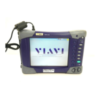
E1/Datacom Tester
to a X.21 circuit
1 Identify the correct cable for the test operation and interface standard:
– If the emulation mode is DTE or DCE Emulation, use one of the X.21
DTE/DCE Emulation cables (part number CB-44390 for up to
2.048 MHz or CB-44391 for up to 10 MHz).
– If the emulation mode is Monitor, use one of the X.21 Y-Monitor cables
(part number CB-44346 for up to 2.048 MHz or CB-44345 for up to
10 MHz)).
2 Connect one end of the adaptor cable to the E1/Datacom Tester’s
universal Datacom connector located on the top panel of the unit.
3 Connect the other end(s) of the adaptor cable to the test access point.
You have finished connecting the cables.
Connecting for RS-232/V.24
and EIA-530 testing
To connect for RS-232/V.24 or EIA-530 testing
1 Identify the correct cable for the test operation and interface standard:
– If the emulation mode is DTE or DCE Emulation, use the RS-232/EIA-
530 DTE/DCE Emulation cable (part number CB-44385).
– If the emulation mode is Monitor, use the RS-232/EIA-530 Y-Monitor
cable (part number CB-44348).
2 Connect one end of the adaptor cable to the E1/Datacom Tester’s
universal Datacom connector located on the top panel of the unit.
3 Connect the other end(s) of the adaptor cable to the test access point.
You have finished connecting the cables.
Connecting for V.35 testing
To connect for V.35 testing
1 Identify the correct cable for the test operation and interface standard:
– If the emulation mode is DTE or DCE Emulation, use the V.35 DTE/
DCE Emulation cable (part number CB-44389).
– If the emulation mode is Monitor, use the V.35 Y-Monitor cable (part
number CB-44341).
2 Connect one end of the adaptor cable to the E1/Datacom Tester’s
universal Datacom connector located on the top panel of the unit.
3 Connect the other end(s) of the adaptor cable to the test access point.
You have finished connecting the cables.
Connecting for RS-449/V.36
testing
To connect for RS-449/V.36 testing
1 Identify the correct cable for the test operation and interface standard:
– If the emulation mode is DTE or DCE Emulation, use the V.36 DTE/
DCE Emulation cable (part number CB-44388).
– If the emulation mode is Monitor, use the V.36 Y-Monitor (part number
CB-44347).
2 Connect one end of the adaptor cable to the E1/Datacom Tester’s
universal Datacom connector located on the top panel of the unit.