FMS-2000C
LIT-12013508
16
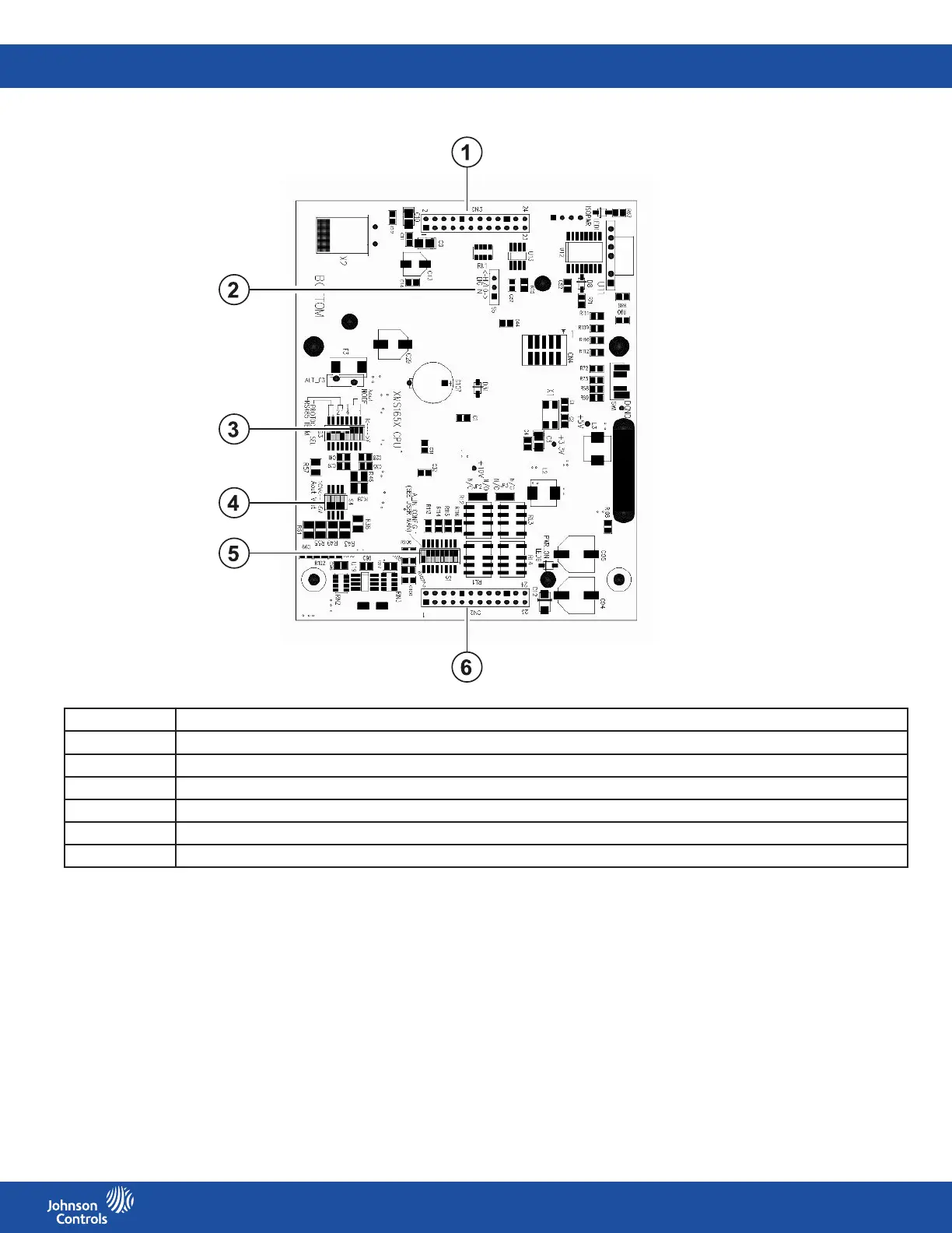
Item DIP switch or connector
1 Back plane interface connector
2 S5 digital input switch
3 S3 analog output configuration, bus termination selection, and protocol selection DIP switch
4 S4 analog output range DIP switch
5 S1 analog input configuration DIP switch
6 Back plane interface connector
Figure 10: Front plane wiring diagram located on the interior front housing of the controller
Table 5: DIP switches and connectors