EasyManuals Logo

Johnson Controls FMS-2000C Installation Guide

Johnson Controls FMS-2000C
49 pages
To Next Page IconTo Next Page
To Previous Page IconTo Previous Page
Page #15 background imageLoading...
Page #15 background image
FMS-2000C
LIT-12013508
15
Step Down
Isolation Transformer
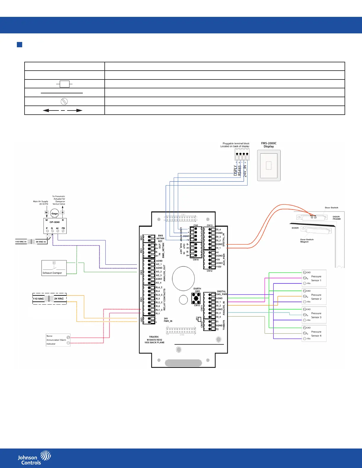
Figure 9: Back plane wiring diagram located on the interior back housing of the controller
Symbol Description
NC No connection to field wiring
Field wiring with space for number
Internal wiring
Screw terminal
Air flow to and from unit between room and corridor
Note: Use this wiring diagrams guide for all of the following wiring diagrams.
Wiring diagrams guide
Table 4: Symbols for wiring diagrams

Other manuals for Johnson Controls FMS-2000C

Questions and Answers:

Question and Answer IconNeed help?

Do you have a question about the Johnson Controls FMS-2000C and is the answer not in the manual?

Johnson Controls FMS-2000C Specifications

General IconGeneral
BrandJohnson Controls
ModelFMS-2000C
CategoryController
LanguageEnglish

Related product manuals