FMS-2000C
LIT-12013508
25
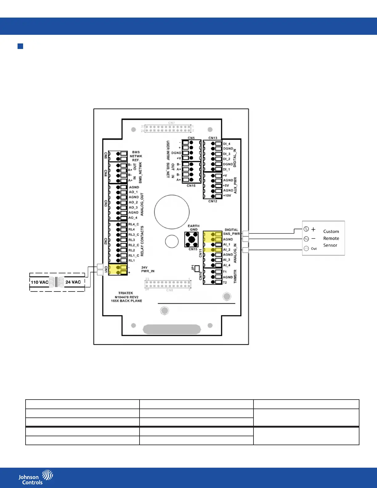
Wiring the analog input to third-party sensor
Note: Figure 19 and Table 12 show the use of AI-2 for a retrot application as an example.
DIP switch ON or OFF Input or output conguration
S1 position 2 OFF AI-2 set as 0 V to 10 V input
S1 position 6 ON
S1 position 2 ON AI-2 set as 4 mA to 20 mA input
S1 position 6 OFF
Figure 19: Third-party sensor wiring diagram
Table 12: Controller conguration DIP switch settings
Step Down
Isolation Transformer
See Table 13 for third-party remote sensor guidelines.