FMS-2000C
LIT-12013508
26
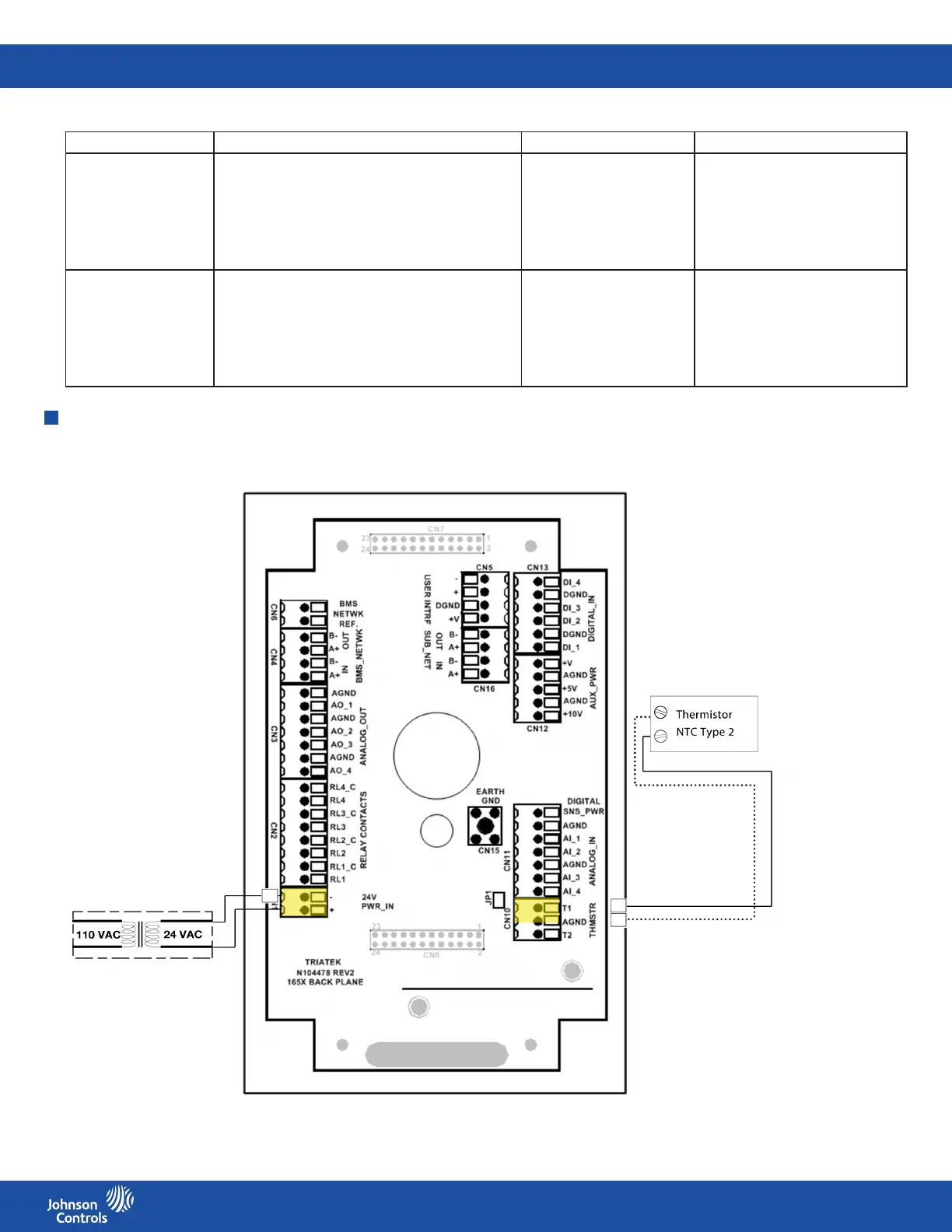
Wiring the analog input for temperature or using a thermistor
Note:
This wiring diagram associates the thermistor with contacts T1 and AGND for illustrative purposes only. In fact, either of the two
thermistors can be used.
Step Down
Isolation Transformer
Analog input Sensor type Pressure range Voltage range
Analog input 1 Differential pressure +/- 0.01 in. (0.25 mm)
+/- 0.05 in. (1.27 mm)
+/- 0.10 in. (2.54 mm)
+/- 0.20 in. (5.08 mm)
+/- 0.25 in. (6.35 mm)
4 mA - 20 mA, default
0 mA - 20mA
0 V - 5 V
0 V - 10 V
1 V - 5 V
2 V - 10 V
Analog Input 2, 3, 4 Differential pressure
Flow, air changes display supported
Temperature
Humidity
CO
2
, AI - 3 and AI - 4 only
Thermostat, AI - 2 only
+/- 0.01 in. (0.25 mm)
+/- 0.05 in. (1.27 mm)
+/- 0.10 in. (2.54 mm)
+/- 0.20 in. (5.08 mm)
+/- 0.25 in. (6.35 mm)
0 V - 5 V
0 V - 10 V
0 mA - 20 mA
1 V - 5 V
2 V - 10 V
4 mA - 20 mA
Figure 20: Temperature sensor wiring diagram
Table 13: Remote sensor guidelines