FMS-2000C
LIT-12013508
11
Determine the desired location of the FMS-2000C display and the device orientation. The FMS-2000C controller display comes pre-
congured for portrait mode but you can also install it in landscape mode. After installing the display, you can adjust the interface
orientation to landscape mode during the initial setup. To complete the mounting of the FMS-2000C controller display for a new
application, make sure you have the following tools:
• #2 Phillips head screwdriver
• 1/16 in. hex wrench
• Drywall saw or oscillating tool with a drywall blade
1. Mount the rough-in box to the side of a framing stud adjacent to entry door to the monitored space. Take the thickness of the wall
into consideration and make sure the front surface is ush or slightly recessed to t with the drywall surface that you install later.
2. Pull the four-conductor interface cable from the controller and the RS-485 BACnet MS/TP wires through the opening in
the rough-in box. The assembly includes a 10 ft cable to connect the display to the controller.
3. Install the drywall ensuring that the mounting surface is ush with the nished surface of the drywall, and the opening ts precisely
with the rough-in box.
4. Take the display’s mounting bracket and align it to the four screw holes on the mounting tabs of the rough-in box. Use a #2 Phillips
head screwdriver to secure the bracket with the screws provided. Ensure the bracket is level.
Note: Do not over tighten the screws or the mounting bracket could get warped.
5. Attach the four-conductor interface cable from the controller and the RS-485 BACnet MS/TP wires on the back of the display. See
label on the back of the display for more information.
6. Align the two slots on the back of the display with the tabs on the bracket and swing the display towards the wall so that the single
tab on the bracket slots into the back of the display.
7. Once the display sits ush against the wall, insert the set screw into the hole in the display housing. Use a 1/16 in. hex wrench to
drive the screw into the display until it engages with the tab on the bracket.
After mounting the FMS-2000C display, apply power to the FMS-2000C. The initial splash screen displays the Johnson Controls logo
and the 360° Safety Halo bezel lights up to represent the current system status.
Mounting the FMS-2000C display for a new application
1
.
5
8
3
in.
1
.
6
6
2
in.
1
.
5
9
6
in.
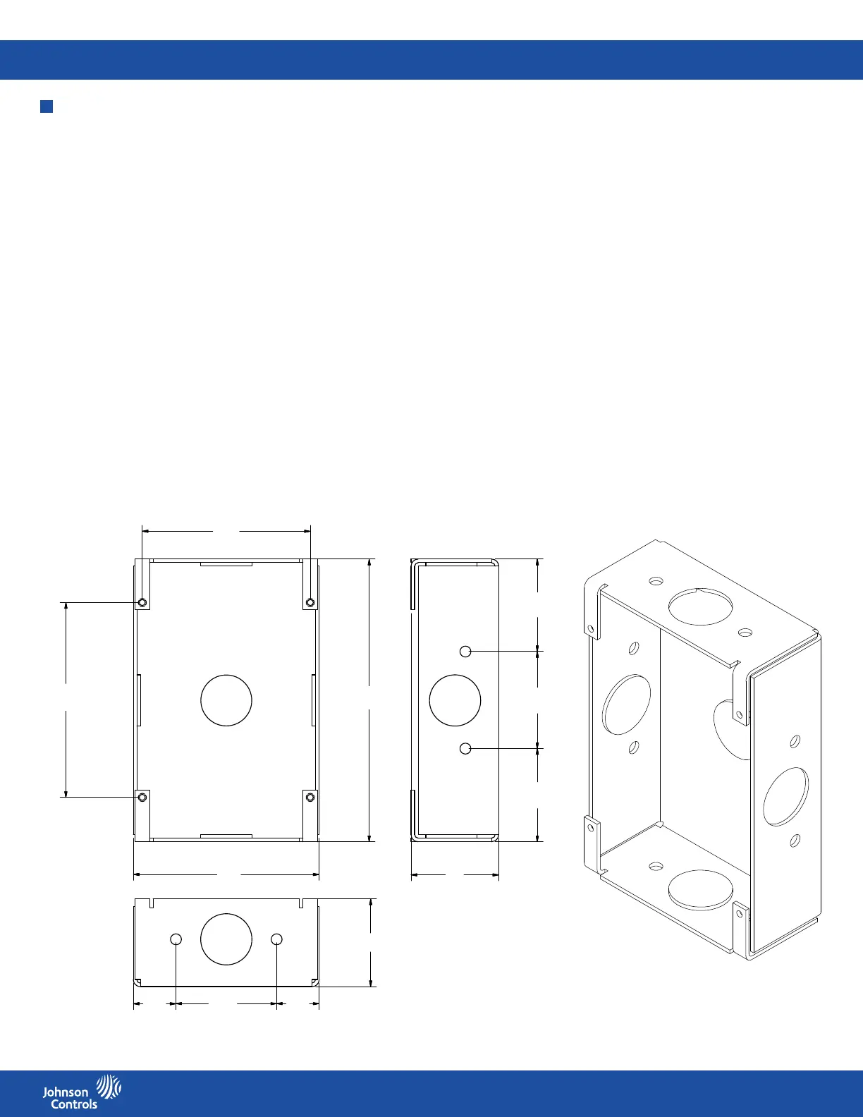
1.5 in.
3.18 in.
2.878 in.
3
.
3
3
8
in.
4
.
8
4
in.
1
.
5
in.
0.728 in.
1.725 in. 0.728 in.
(84.785 mm)
(122.94 mm)
(40.208 mm)
(42.215 mm)
(40.538 mm)
(73.101 mm)
(80.77 mm)
(38.1 mm)
(18.491 mm) (43.815 mm) (18.491 mm)
(38.1 mm)
Figure 5: Rough-in box dimensions
Figure 6: Rough-in box