CONTROL SYSTEM
6-40
TC-15001-rev.3
4
)ROORZWKHSURFHGXUHVIURPWRWRDWWDFKWKH,5UHFHLYHUNLWRQWKHGHFRUDWLYHSDQHO
5
,QVWDOOWKHGHFRUDWLYHSDQHOWRWKHLQGRRUXQLWDFFRUGLQJWRWKH³,QVWDOODWLRQDQG0DLQWHQDQFH0DQXDO´IRU
the decorative panel.
6
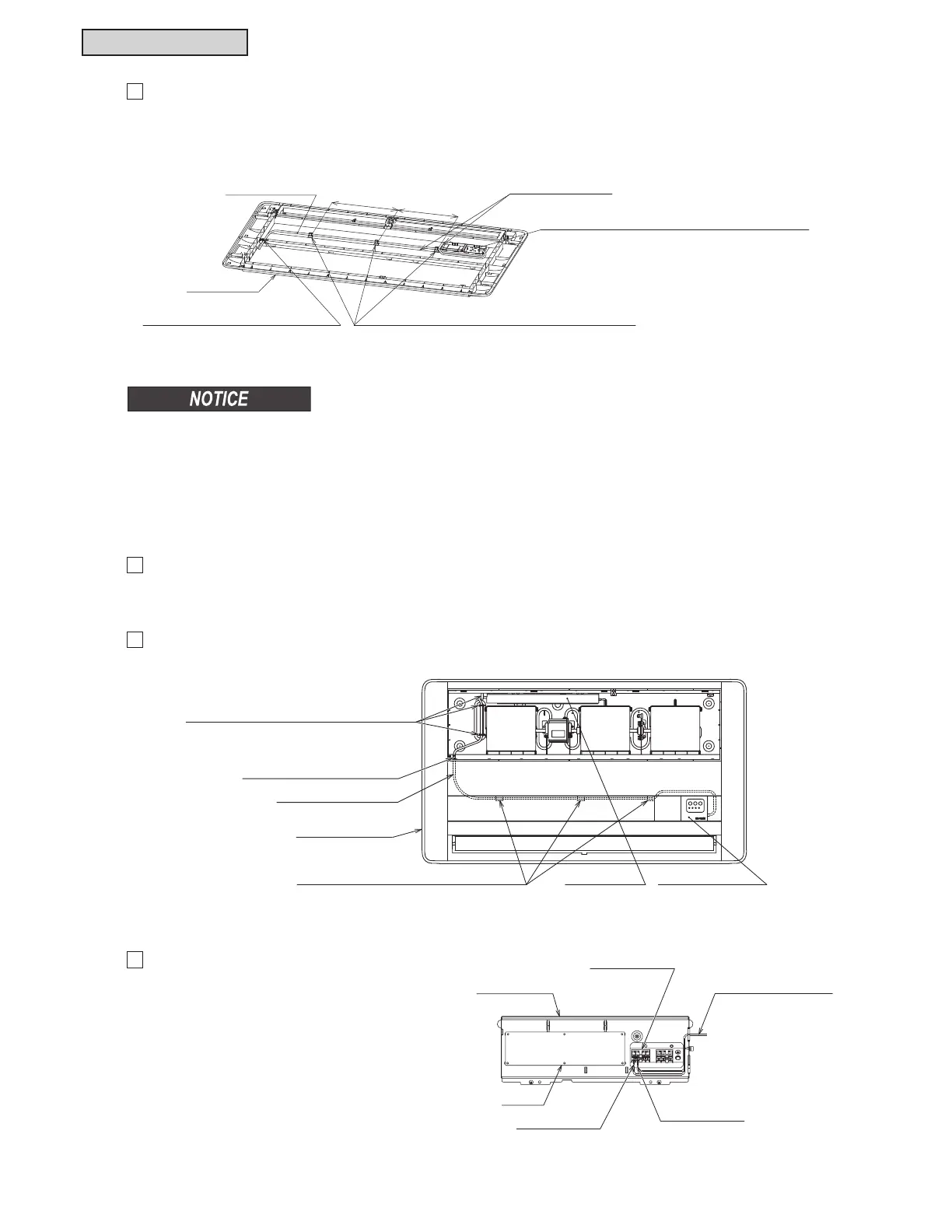
6HFXUHWKH,5UHFHLYHUNLWFDEOHZLWKWKHFDEOHFODPSRIWKHLQGRRUXQLW
7
Remove the electric box cover of the indoor
XQLW&RQQHFWWKH,5UHFHLYHUNLWFDEOHWRWKH
WHUPLQDOEORFNV$%LQWKHHOHFWULFER[DV
shown at the right. (Terminals A and B have no
polarity.)
Ɣ 3D\SDUWLFXODUDWWHQWLRQWRWKHLQVWDOODWLRQGLUHFWLRQRIWKH,5UHFHLYHUNLW1XPEHURIFRXSOLQJKRRNVRI
the IR receiver should match the notches at the installation position.
Ɣ &KHFNWRHQVXUHWKDWWKH,5UHFHLYHUNLWLVVHFXUHO\LQVWDOOHG
Ɣ %HVXUHWRDWWDFKWKHFDEOHFODPSDFFHVVRU\DFFRUGLQJWRWKHUHTXLUHGSRVLWLRQ
If not, condensation may occur because of a space between decorative panel and the indoor unit.
Decorative Panel
Cable Clamp (Accessory)
Attaching Position
(1) Insert the IR receiver kit and cable into the attachment position.
Attach the coupling hooks (three portions) of the IR receiver kit
and the notches at the attachment positions securely.
(3) Pull out the IR receiver kit cable
through the hole of the decorative panel.
IR Receiver Kit Cable
(2) Attach the cable clamp (accessory) at the rear side
of the decorative panel to secure the IR receiver kit cable.
8 (203)
12 (304)
Unit: inch (mm)
Cable Through-Out Hole at
Optional Decorative Panel
Decorative Panel
Insert the IR receiver kit cable into
the cable clip at the indoor unit side,
and secure it. (three places)
IR Receiver KitElectric Box
IR Receiver Kit Cable
Cable Clamp (Accessory) (three places)
Terminal Block
PCB
Electric Box
IR Receiver Kit Cable
Mark Band “A”
Mark Band “B”
 Loading...
