CONTROL SYSTEM
TC-15001-rev.3
6-103
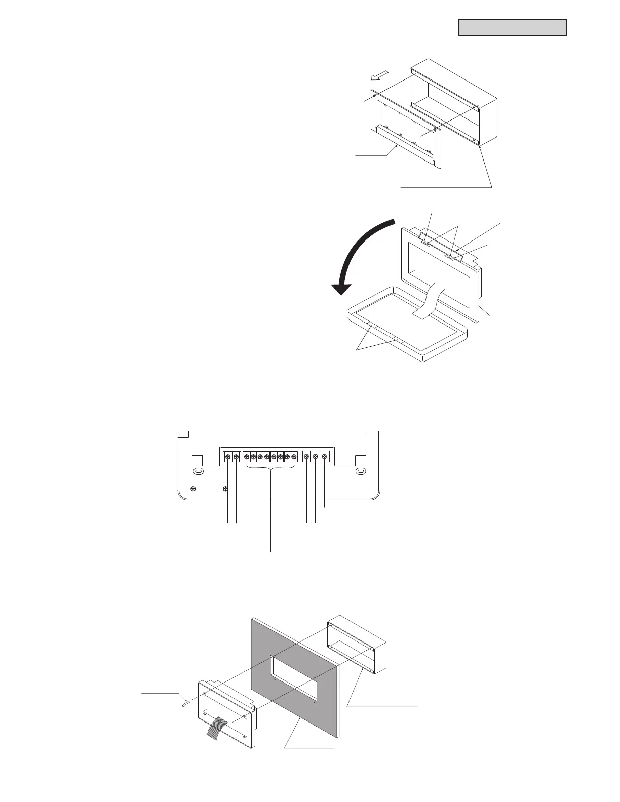
[Installation Method]
(1) Remove the cover attached to the optional steel
box.
(2) Install the optional steel box into the wall.
(4) Connect the wiring to the terminal board of the large central controller.
TB1: Terminal Board for Power Supply
TB2: Terminal Board for H-LINK
TB3: Terminal Board for External Input and Output
(5) Mount the optional steel box with the M4 x 5/8 inch accessory mounting screws.
(3) The factory ships the unit body open.
If the unit is closed, open it as shown at right.
(a) Open the lid of unit body.
(b) While pressing both latches, the top of the
case can be opened since the catches for
mounting have been removed.
Cover
Steel Box (Option)
Optional Steel Box
M4 Screws
(Q’ty. 4)
Wall Surface
Optional Steel Box
Upper
Case
Catch for Fixing
Hook
Catch for Fixing
Convex Part
Top Cover
Latch
Latch
Slots
Convex Part
Lower Case
TB2 TB3 TB1
H-LINK
(Non-pole)
FG
24VAC
Terminals for external input/output
Refer to item 6.9.10.13.
 Loading...
