CONTROL SYSTEM
6-102
TC-15001-rev.3
6.9.5 Accessories
Ɣ6WHHO%R[7\SH
6.9.6 Installation
This manual provide information on installation for a test run of the large central controller.
The installation procedures should be performed as shown below.
Preparation at the Site
Start
Installation
Switch Setting
Wiring
Test Run
6.9.6.1 Preparation at the site
Before installing a controller, prepare the following items.
Parts 6SHFL¿FDWLRQ
Steel Box Option
Power Supply
Cable
Cable SPEC: AWG 16(1.25mm
2
) to AWG 14(2mm
2
)
Recommended Cable: 600V CV, CCV, CEV
H-LINK Cable
(For Control)
Cable SPEC: AWG 18(0.75mm
2
) to AWG 16(1.25mm
2
)
Recommended Cable: Shielded Communication Cable
Over AWG 18(0.75mm
2
) (Equivalent to KPEV-S)
6.9.6.2 Installation
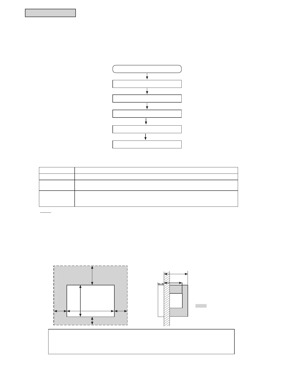
[Installation Space]
0DLQWDLQVXI¿FLHQWVSDFHIRUWKHLQVWDOODWLRQRIWKHODUJHFHQWUDOFRQWUROOHUDVVKRZQEHORZ
NOTE:
Communication cabling shall be a minimum of 18-Gauge, 2-Conductor, Stranded Copper. Shielded cable must be considered for
applications and routing in areas of high EMI and other sources of potentially excessive electrical noise to reduce the potential for
communication errors. When shielded cabling is applied, proper bonding and termination of the cable shield is required as per
Johnson Controls guidelines. Plenum and riser ratings for communication cables must be considered per application and local code
requirements.
When installing more than two large central controllers in row or in line, maintain adequate
spacing between each.
* Vertical Direction: 4 Inches (102mm)
* Horizontal Direction: 2 Inches (51mm)
Unit: inch (mm)
Do not attach anything
in the shaded area
“
”.
4 Inches
(102)
2-3/16
Inches
(56)
1
Inch
(25)
2-3/4
(70)
7 Inches
(178)
10 Inches
(254)
2 Inches
(51)
2 Inhes
(51)
2 Inches
(51)
 Loading...
