CONTROL SYSTEM
TC-15001-rev.3
6-105
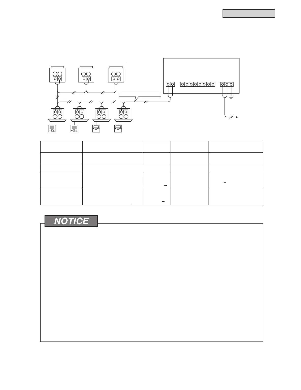
6.9.8 Electrical Wiring
(1) The large central controller requires wiring of the power supply cable, air conditioner, and control wiring
(H-LINK).
(2) Wiring Method
Type of Wiring 6SHFL¿FDWLRQ
Length
of Wiring
Cable
6SHFL¿FDWLRQ
Recommended
Cable Model
Power Supply
Cable
24VAC -
AWG16(1.25mm
2
)
to AWG14(2mm
2
)
600V CV, CCV, CEV
Ground Cabling --- --- --- ---
H-LINK
(Control Cable)
5VDC
3281feet
(1000m) >
AWG18 (0.75mm
2
)
to AWG16
(1.25mm
2
)
Communication Cable with
Shield > AWG18(0.75mm
2
)
(Equivalent to KPEV-S)
Wiring for External
Input and Output
Input:
Non-voltage Normal Open
Output: 12VDC, 75mA>
230 feet
(70m) >
AWG18 (0.75mm
2
)
to AWG16
(1.25mm
2
)
JKPEV-S, JKEV-S,
CVV-S, CVV, 600V VCT
Ɣ The large central controller may break down by an incorrect wiring.
Ɣ Communication cabling shall be a minimum of 18-Gauge, two-Conductor, Stranded Copper.
Shielded cable must be considered for applications and routing in areas of high EMI and other
sources of potentially excessive electrical noise to reduce the potential for communication errors.
When shielded cabling is applied, proper bonding and termination of the cable shield is required
as per Johnson Controls guidelines. Plenum and riser ratings for communication cables must be
considered per application and local code requirements.
Ɣ It is a requirement that communication cables be separated from the power supply wiring and other
electrical device wiring. Maintain at least 12 inches (30cm) separation between communication
cables and wiring from the power supply. If wiring and cables are not secured separately, they
should be run through separate metal conduit tubing. One side of the metal conduit tubing should be
grounded for noise reduction.
Ɣ Do not connect the power supply wiring to the large terminals for communication at of large central
controller. If the power supply wires are connected incorrectly, the fuse of the printed circuit board will
blow out for protection. If this happens, turn ON DIP switch (DSW2-pin) on the printed circuit board
(PCB), to proceed with unprotected (no fuse) emergency operation.
Ɣ :KHQDQLQVXODWLQJFDSDFLW\WHVWRUYROWDJHWHVWLVSHUIRUPHG¿UPO\UHPRYHWKHJURXQGZLULQJRI
the ground fault termina
l.
Wired Controller
Indoor Unit
Outdoor Unit
CCL01
1
123456
2
Connect the
transmission wires to
the TB terminals
and of the outdoor
units and the indoor
units.
H-LINK (Communication Cable)
Terminal
Board
TB2
Terminal
Board
TB3
Power Supply
24VAC
12
FG
Frame Ground
Terminal
Terminal
Board
TB1
1
1 1 1 1
1 1
1
2
2 2 2
2
2
2
2
7
8
Connect the
Communication cables
to the TB terminals
(TB1) and (TB2) for
the indoor and outdoor
units.
 Loading...
