38
Hardware Installation—Installing the
IFC-1010/2020
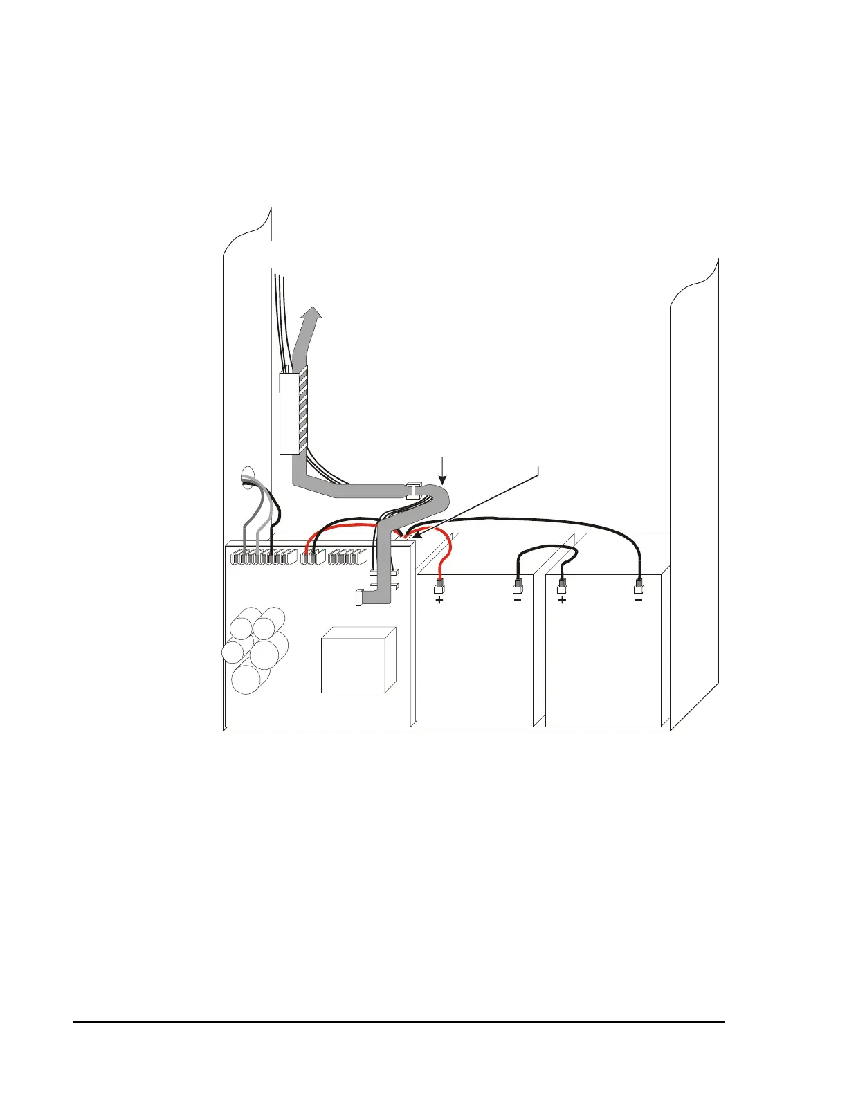
Figure 30 depicts a typical IFC-1010/2020 installation and is provided as a
guide for proper wiring placement. The AC and battery wiring are not
power-limited. A separation of at least 1/4 inch must be maintained
between power-limited and non power-limited wiring. Install the tie wraps
and adhesive squares as indicated in Figure 30.
powwire2
12 VDC
Battery
12 VDC
Battery
12 VDC
Battery
12 VDC
Battery
MPS-24A/E
To XPP-1
Plug P7
Adhesive square and
tie wrap on back of cabinet
affixing power-limited wiring.
Adhesive square and
tie wrap on top of power
supply chassis affixing
non power-limited wiring.
CAB-3
Cabinet
To XPP-1
Plug P9
Figure 30: Power-Limited and Non Power-Limited Wiring