Hardware Installation—Installing the IFC-1010/2020
39
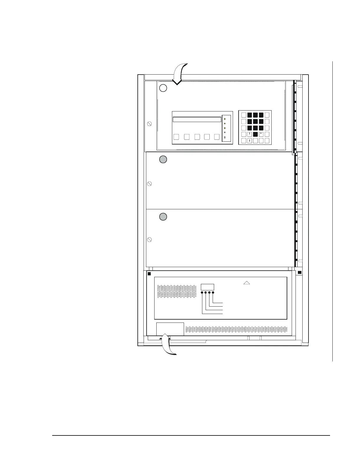
Figure 31 is provided as a guide for dress panel placement.
panelplc
DP-1 Dress Panel
INTELLIGENT FIRE DETECTION AND ALARM SYSTEM
JOHNSON CONTROLS IFC-1010
ALL SYSTEMS NORMAL 04:08P 01/01/92
SIGNAL
SILENCE
SYSTEM
RESET
SYSTEM
TEST
LAMP
TEST
ACK/
STEP
A.C.
POWER
SYSTEM
ALAR M
SYSTEM
TRO UBLE
DISPLAY
TRO UBLE
SIGNAL
SILENCE
READ
STATUS
ALTER
STATUS
PROG
SPL
FUN CT
ALPH A
ENTER
NEXT
AUTO
STEP
ENTER
BACK
SPACE
PRIOR
12
3
4
5
6
789
0
ACK/
STEP
SIGNAL
SILENCE
SYSTEM
RESET
SYSTEM
TEST
LAMP
TEST
Ground Fault
Ground Fault
Battery Fail
AC Power Fail
CAUTION
120 VAC UNDER PANEL
WARNING
Several Different Sources of Power can be
Connected to this Control Unit. Disconnect
all Sources of Power Before Servicing.
DP-1 Dress Panel
BP-3 Battery Dress Panel
DIA-1010 or DIA-2020
!
Figure 31 : Dress Panel Placement Diagram