IFC-3030 Installation Manual — P/N 52024:C 08/05/2005 13
Product Diagram System Overview
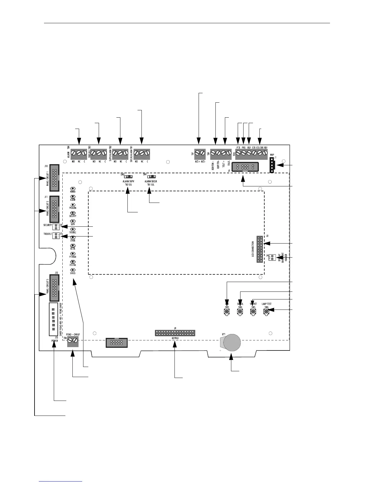
2.3 Product Diagram
The control panel electronics are contained on one printed circuit board (PCB) that holds the
central processing unit (CPU). The CPU can be purchased with or without keypad and display; (see
Section 2.2 “System Components” for P/N details). Connections are identical on both versions. The
following figure illustrates the location of the various connections, switches, jumpers and LEDs on
the circuit board. See Section 3 “Installation” for more details.
J4 backlight
connection
J2 LCD connection
SW3 Acknowledge
SW4 Signal Silence
SW5 System Reset
SW6 Lamp Test
Lithium battery for backup of
on-board memory (See Section 3.5.1
“Memory-Backup Battery”.)
Test fixture:
Status Indicator LEDs (See Figure 2.3)
J9 Keypad connection
Service-level switches
for local operation
without keypad/display
J13 Power connections (non-power-limited)
(See Section 3.15 “Connecting Power Sources and Outputs”)
J6 Security switch connection
J5 Trouble bus connection
SW2 Supervisory
SW1 Security
J7 SLC Loops
(Connect to
first LCM-320)
Cable P/N 75565
J1 Network/Service
Connection (NUP)
Cable P/N 75556
TB4 Alarm Relay
TB3 Trouble Relay
TB2 Supervisory Relay
TB1 Security Relay
J10, J11, J12 Panel circuit module connections
(power-limited, supervised) Cable 71088 (See Figure 3.9)
Note: Relay circuits are power-limited only if
connected to a power-limited signal source.
Relays are rated for 2A@30Vdc resistive.
Note: Dotted line indicates location of optional keypad & LCD display
TB9 TOUT+/- : Future Use
TB7 ACS (power-limited, supervised)
TB5, CTS/CRX Keltron printer
supervision
(TB5, CTS & REF No connection)
TB5, left side. Printer (isolated)
3030board.cdr
TB6 Accessory Power (See
Section 3.15 “Connecting Power
Sources and Outputs”)
TB9 RDP devices such as LCD-160
Figure 2.1 CPU Connections

 Loading...


