IFC-3030 Installation Manual — P/N 52024:C 08/05/2005 23
Attaching the CPU & Chassis Installation
Note for JCPU-3030D Due to the difficulty of reaching under the keypad, it may be convenient
to remove the insulator from the lithium memory-backup battery at this time. See Section 3.5.1
“Memory-Backup Battery”.
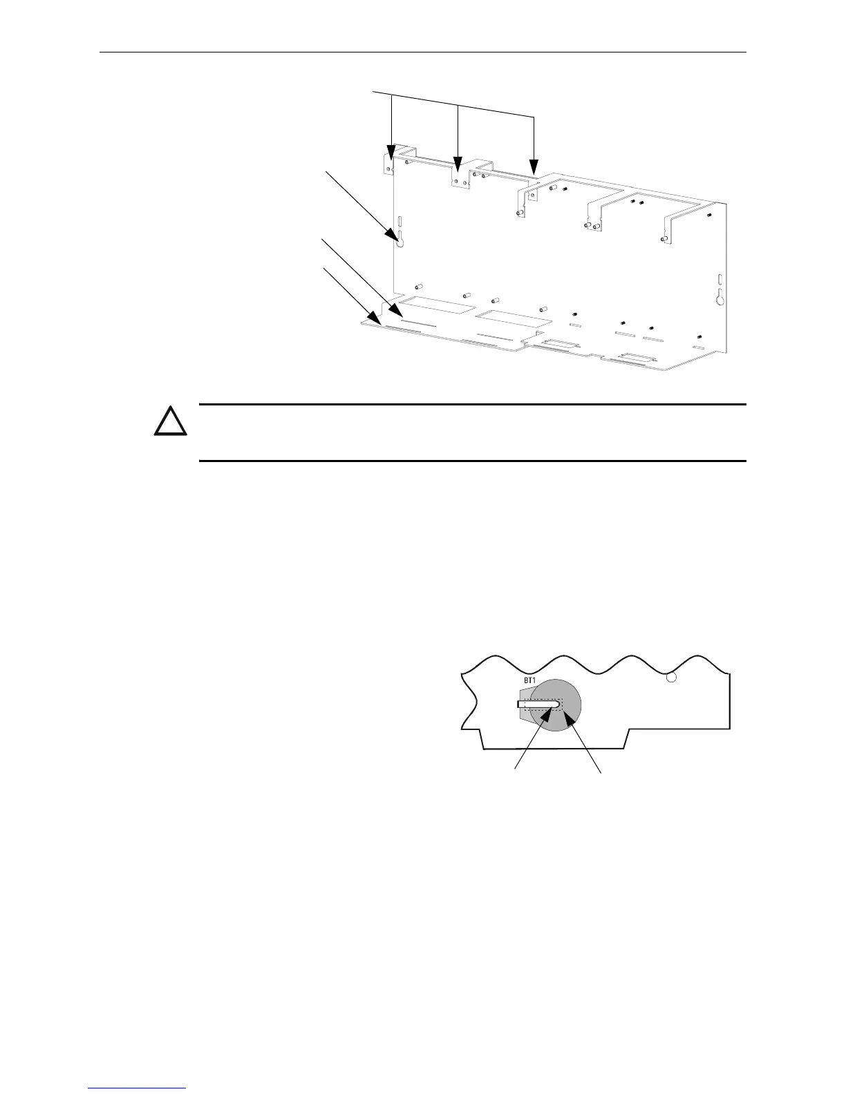
Mounting Chassis in Backbox
Align chassis-mounting slots with chassis-mounting studs (see Figure 3.1 and Figure 3.4 for
locations). Secure with nut & lock-washer provided with chassis.
3.5.1 Memory-Backup Battery
The lithium battery on the CPU provides
backup of the CPU’s on-board memory
during power loss. The CPU ships with an
insulator to prevent the battery from
discharging. To preserve the battery, the
insulating tube should be left in place as
long as possible before applying AC
power.
If the insulator is not removed before
applying AC power, the control panel will
show a trouble situation.
This battery’s shelf-life should exceed 10 years, but if for some reason it fails, the control panel will
show a trouble when powered up. To replace the lithium battery:
1. Make a full backup of all system settings to prevent loss of all programming data.
2. Disconnect all power sources.
3. JCPU-3030D only: Disconnect wiring and remove JCPU-3030D from backbox (3 screws at
top, lift board tabs out of slot) and remove keypad (4 screws on back, LCD display stays
attached).
!
CAUTION:
It is critical that all mounting holes of the IFC-3030 are secured with a screw or stand-off to insure
continuity of Earth Ground.
CPU standoffs at Positions 1 and 2:
1.5 inch (38.1 mm) for use with JCPU-3030D
or 0.25 inch (6.35 mm) for use with JCPU-3030ND
CHS-M3.cdr
JCPU-3030ND
(without keypad/display)
JCPU-3030D
(with keypad/display)
Chassis-mounting slots
Figure 3.4 Standoffs on Chassis CHS-M3
Lift clip gently while
removing battery
Dotted line indicates
location of insulator
3030-lithium.cdr

 Loading...


