IFC-3030 Installation Manual — P/N 52024:C 08/05/2005 21
Laying Out Equipment in Cabinet and Chassis Installation
2. Select and punch open the appropriate knock-outs. (For selection guidelines, see Section 3.16
“UL Power-limited Wiring Requirements”.)
3. Using the keyholes, mount the backbox over the two screws.
4. Mark the location for the two lower holes, remove the backbox and drill the mounting holes.
5. Mount the backbox over the top two screws, then install the remaining fasteners. Tighten all
fasteners securely.
6. Feed wires through appropriate knockouts.
7. Install CPU and other components according to this section, before installing hinges and door
(see CAB-3/CAB-4 Series Cabinet Installation Document).
3.4 Laying Out Equipment in Cabinet and Chassis
The IFC-3030 allows for flexible system
design. Follow these guidelines when
deciding where to locate equipment in the
backbox. There are four basic positions
available on a chassis; the number of
layers that can be mounted in each
position depends on the chassis model
and the module size.
The CPU mounts in chassis CHS-M3 in
the top row of the cabinet. The CPU and
its optional display occupy the left half of
the chassis (positions 1 and 2, see Figure
3.2). If JNCA is used, it may be
door-mounted in front of a displayless
CPU (see the JNCA manual for details &
restrictions).
Positions 3 and 4 of CHS-M3 can hold up to four layers of equipment including annunciators, panel
circuit modules, and option boards. See Figure 3.3 for possible configurations of these four layers.
The BMP-1 Blank Module Plate covers unused positions and also provides a location to
door-mount some option boards (see BMP-1 Product Installation Drawing for details).
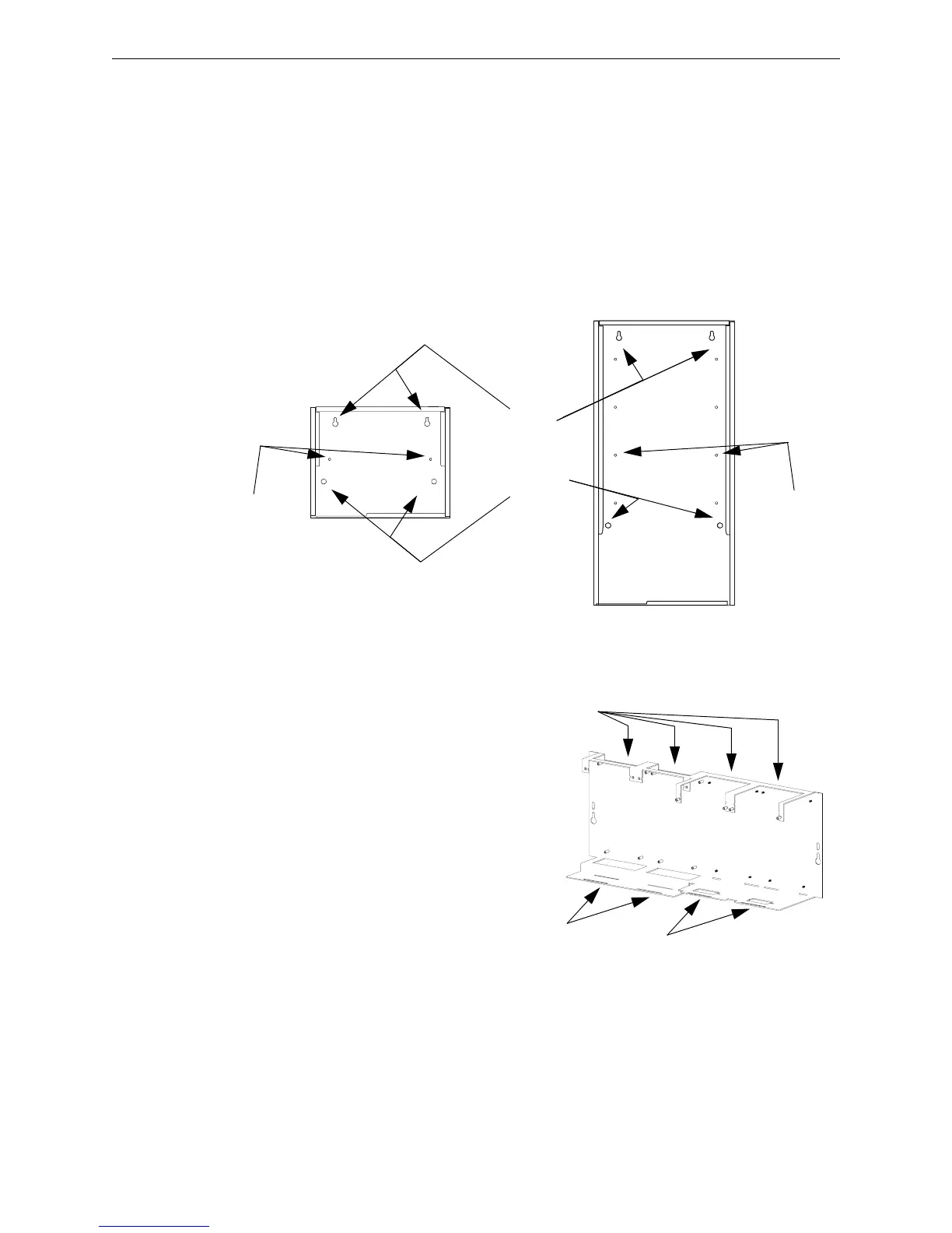
Keyholes
2 places
Mounting holes
2 places
CAB-4 Series backbox,
A-size (one-row)
CAB4cabinetmountingholes.cdr
CAB-4 Series backbox,
D-size (four-row)
Chassis-mou
nting
studs
(2 per row of
backbox)
Chassis-mount
ing
studs
(2 per row of
backbox)
Figure 3.1 Backbox-Mounting Holes and Chassis-Mounting Studs
Figure 3.2 Chassis CHS-M3
12 34
Four positions
on chassis
CHS-M3
Positions 3 and 4:
Four layers of equipment
Positions 1 and 2:
CPU
CHS-M3.cdr

 Loading...


