22 IFC-3030 Installation Manual — P/N 52024:C 08/05/2005
Installation Attaching the CPU & Chassis
Second, third, and fourth rows of equipment use any chassis compatible with CAB-4 series
backboxes, such as CHS-4N (shipped as part of CHS-4MB) or CHS-4L. Refer to the CAB-3/CAB-4
Series Cabinet Installation Document for a complete list. Some equipment (such as the JNCA and
annunciators) can be door-mounted; refer to your equipment’s documentation for instructions.
Panel circuit modules include ICM-4RK, CRM-4RK, IZM-8RK, VCM-4RK, DCM-4RK and their
expanders. See Section 3.7 “Attaching Panel Circuit Modules”; for VCM-4RK and DCM-4RK,
also see the Voice Alarm System Manual. Option boards include LCM-320, LEM-320, NCM-W/F,
TM-4, and DPI-232; see Section 3.6 “Attaching Option Boards”. The documentation shipped with
your equipment may also contain device-specific instructions.
3.5 Attaching the CPU & Chassis
Mount CPU into positions 1 and 2 of CHS-M3 as follows; equipment may be mounted to the
chassis before or after the chassis is mounted in the backbox. Some equipment may be
door-mounted directly in front of the CPU; see Section 3.4 “Laying Out Equipment in Cabinet and
Chassis” and the manual shipped with the other device.
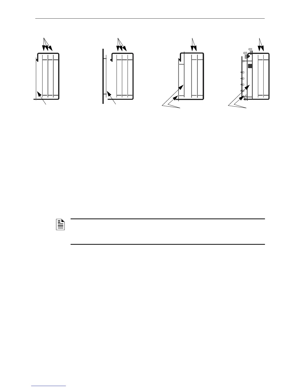
1. Attach four stand-offs to chassis as shown in Figure 3.4.
JCPU-3030D (with keypad/display) requires the longer stand-offs: 1.5 inch (38.1 mm);
JCPU-3030ND (without keypad/display) requires the shorter stand-offs: 0.25 inch (6.35 mm)
2. Slide circuit-board tabs into slots on chassis as shown in Figure 3.4.
3. Place the board over the stand-offs so that mounting holes line up with those on the chassis.
Secure all stand-offs with screws provided.
Layer 4 mounted to
PEM studs and tab-slot
Layer 4 door-mounted*
Layers 1&2&3 mounted to
PEM studs on chassis
Layers 1&2&3 mounted to
PEM studs on chassis
Layers 1&2 mounted to
PEM studs on chassis
Layers 1&2 mounted to
PEM studs on chassis
Layer 4 mounted to PEM
studs and tab-slot; Layer 3
suspended from Layer 4
Layer 4 mounted to PEM
studs and tab-slot; Layer 3
suspended from Layer 4
CHS-M3-options.cdr
*Note: If CHS-4N is used, door-mounting is only for use with
ACM-24AT and ACM-48A series annunciators.
Figure 3.3 Configuring Equipment in Chassis (Side View):
Positions 3 and 4 of CHS-M3, All 4 Positions of CHS-4N
NOTE: It is recommended that system design take into consideration the UL requirements for
minimum separation of power-limited and non-power-limited wiring; for example, having all
non-power-limited circuits grouped in one area of the cabinet (see Section 3.16 “UL Power-limited
Wiring Requirements” and your power supply manual).

 Loading...


