24 IFC-3030 Installation Manual — P/N 52024:C 08/05/2005
Installation Attaching Option Boards
4. Remove battery from under clip (use fingers, because screwdriver could damage components)
and insert new battery.
5. JCPU-3030D only: Replace keyboard, reinstall JCPU-3030D into chassis, and reconnect
wiring.
6. Follow system power-up procedures.
7. Dispose of used battery promptly. Keep away from children. Do not disassemble and do not
dispose of in fire.
3.6 Attaching Option Boards
If installing option boards
into a CAB-4 Series
backbox, mount &
connect those boards at
this time. This section
contains general
instructions for mounting
an option board; see the
documentation that
shipped with your board
for any product-specific
instructions.
As described in Section
3.4 “Laying Out
Equipment in Cabinet and
Chassis”, up to eight
option boards can be
mounted in CHS-M3 to
the right of the CPU;
additional modules can be
mounted in other chassis.
There are no slots in the first (back) two layers, but option boards with tabs (such as NCM-W) will
still fit in those positions.
Mounting procedures
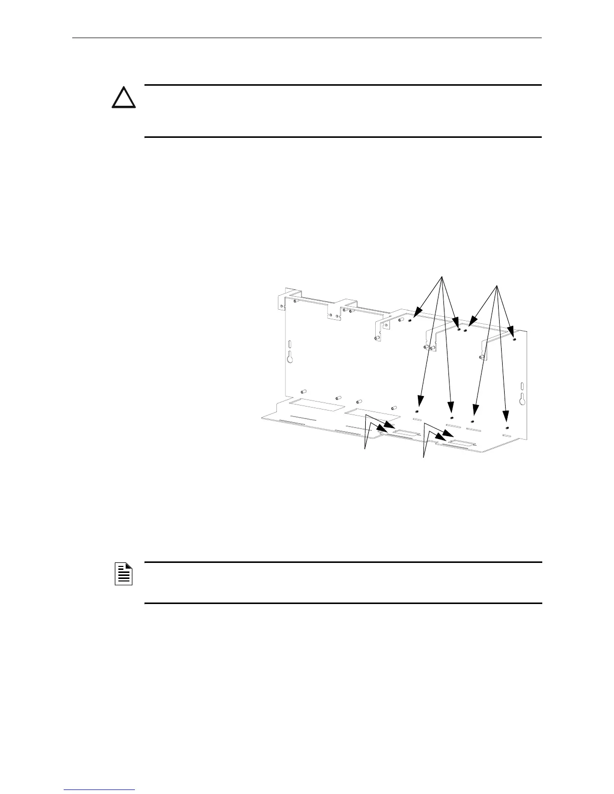
1. Install four 1 inch (25.4 mm) stand-offs onto the chassis as shown in Figure 3.5.
2. Place the first option board over the stand-offs so that holes line up.
3. If no more option boards will be mounted in that position, securely fasten all stand-offs with
screws (provided with module). If mounting a second or third option board, attach another
layer of stand-offs and repeat steps 2-3. Note: Set the switches on an option board before
mounting another layer in front of it.
4. If mounting a pair of SLC loop modules, refer to Section 3.14.2 “Loop Control Module, Loop
Expander Module” and to Section 3.7.3 “Installing a Multi-layer Module into the Chassis”.
!
CAUTION:
The battery used in this device may present a risk of fire or chemical burn if mistreated.
Do not recharge, disassemble, heat above 212°F (100°C), or incinerate. Replace battery with
Notifier P/N LITHBATT-3V only. Use of another battery may present a risk of fire or explosion.
CHS-M3.cdr
Attach stand-offs for
option boards here...
...and here
Figure 3.5 Mounting Option Boards in CHS-M3
When applicable, slide tabs at
bottom of option boards here...
...and here
NOTE: Mounting two pairs of LCM-320 and LEM-320 modules in one chassis possition may
cause intermittent electrical interference. If this occurs, move one pair to a separate chassis
position.

 Loading...


