IFC-3030 Installation Manual — P/N 52024:C 08/05/2005 55
Fire/Security Applications Applications
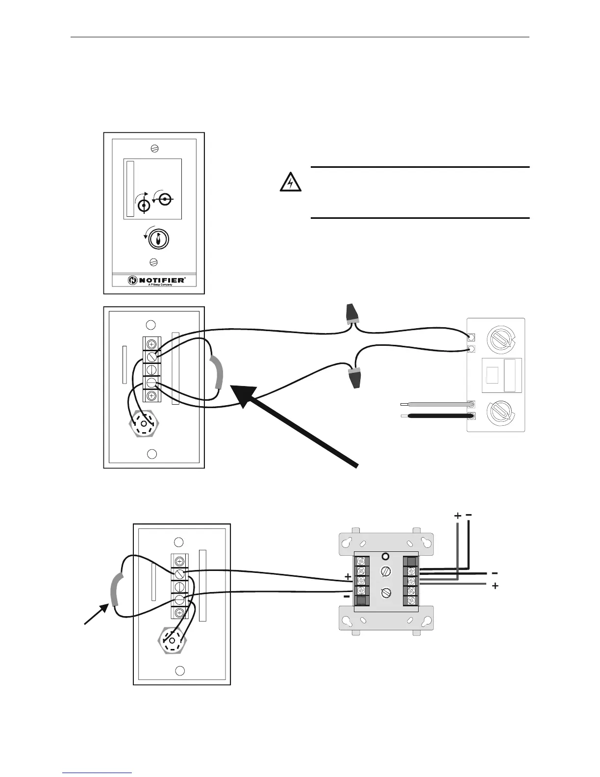
4.5.7 Connecting an RKS-S Remote Key Switch
The RKS-S Remote Key Switch arms and disarms the system. It can be mounted in a UL listed
single-gang electrical box. Both the monitor module and RKS-S must be mounted within the
protected area. Figure 4.6 and Figure 4.7, respectively, depict the connection of the M301MJ or
M300MJ module to the RKS-S.
0
10
11
12
13
14
15
ADDRESS
LOOP
1
2
3
4
TENS
ONES
6
7
8
9
5
0
1
2
3
4
6
7
8
9
5
SECURITY
SYSTEM
ARM
DISARM
Wire an R-47K End-of-Line
Resistor into the circuit
RKS-S
front
yellow (–)
RKS-S
rear
purple (+)
Signaling
Line
Circuit
red (+)
black (–)
RKSFMM-a.cdr
Figure 4.6 Connecting the M301MJ Module to the RKS-S
!
WARNING:
XP Transponder circuits (XPP-1, XPM-8, XPC-8,
XPR-8, XPM-8L) are not suitable for
security applications.
M301MJ
8
9
8
8
9
9
10
11
12
13
14
150
0
1
1
2
2
3
3
4
4
5
5
6
6
7
7
0
1
2
3
4
7
6
5
TENS
ONES
DDRESS
LOOP
RKS-S rear
M300MJ
RKSFMM-b.cdr
SLC Out
SLC
In
Wire an
R-47K
End-of-Line
Resistor into
the circuit
Figure 4.7 Connecting the M300MJ Module to the RKS-S

 Loading...


