48 IFC-3030 Installation Manual — P/N 52024:C 08/05/2005
Installation Connecting a PC for Programming
3.19.3 Installation
Install loop control and expander modules as described in Section 3.14.2 “Loop Control Module,
Loop Expander Module”. Note that the unique SLC loop number assigned to a module does not
need to match the module’s location in the cabinet. For details on designing, installing and
configuring SLC loops, see the Johnson Controls SLC Wiring Manual.
3.20 Connecting a PC for Programming
A PC running the VeriFire™ Tools programming utility can upload and download the operating
program of the control panel when attached to J1 Network/Service Connection (NUP) or to the
second Network/Service connection on an attached NCM-W/F. Refer to the VeriFire™ Tools CD
for instructions.
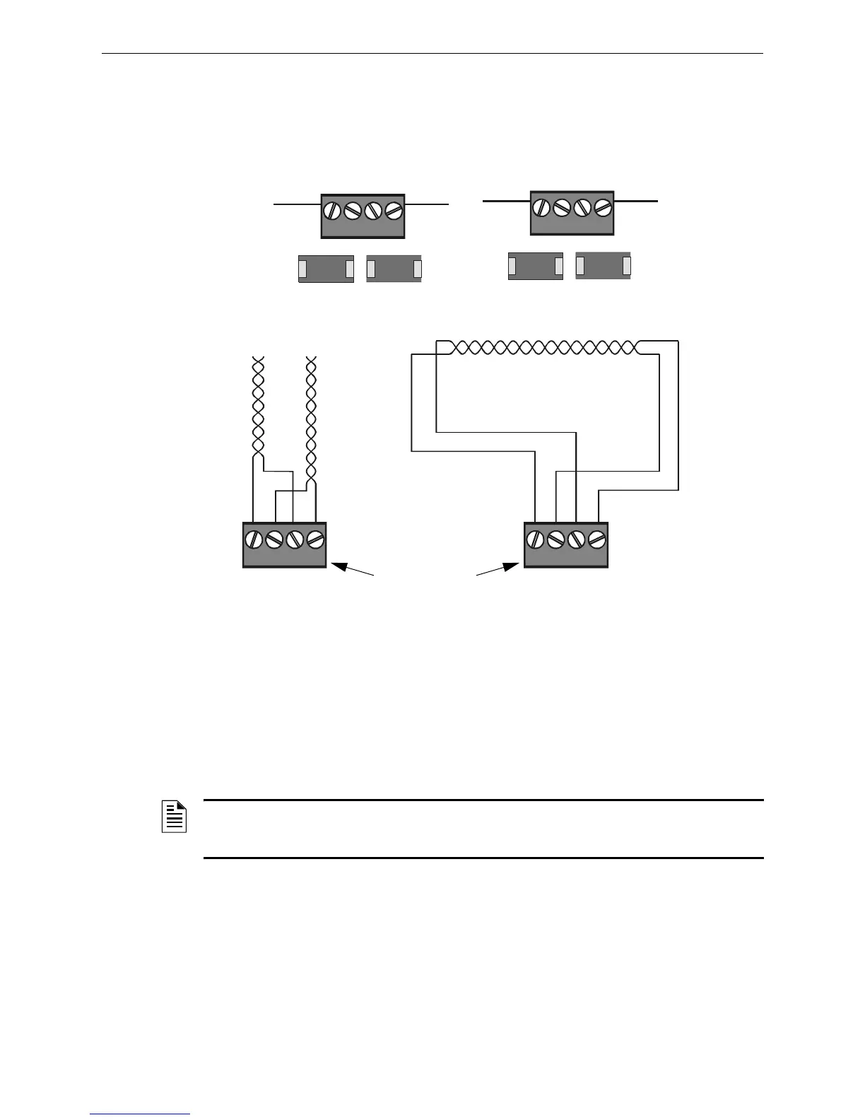
B+ A+ B- A- B+ A+ B- A-
T-Tapping is not allowed
on a four-wire SLC.
Channel B (output loop)
Channel A (loop return)
Style 4 SLC Loops
Style 6 SLC Loops
TB1
B+ A+ B- A-
SLC Loop #2 Connections
on Loop Expander Module
SLC Loop Connections
on Loop Control Modules
SLC loop
connections are
the same for Loop
Expander and
Control Modules
TB1
B+ A+ B- A-
Channel
B
Channel
A
3030-slcloops.cdr
Figure 3.28 SLC Loop Connections and Wiring
NOTE: Download operations that change the basic program of the control panel must be
performed by responsible service personnel in attendance at the control panel. After downloading
a program, test the control panel in accordance with NFPA 72-1999.

 Loading...


