IFC-3030 Installation Manual — P/N 52024:C 08/05/2005 33
Form-C Relays on the CPU Installation
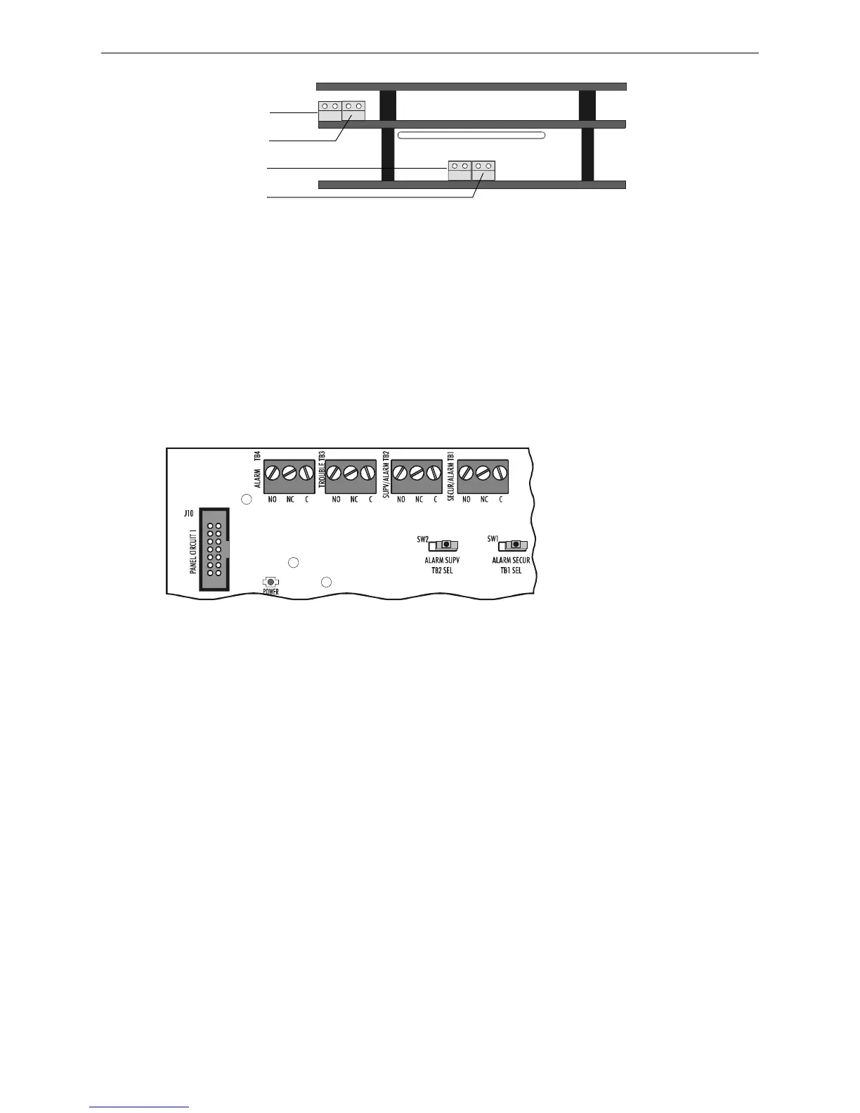
3.10 Form-C Relays on the CPU
The panel provides a set of Form-C relays. These are rated for 2 A at 30 VDC (resistive):
• Alarm - TB4
• Trouble - TB3
• Supervisory - TB2
• Security - TB1
The Supervisory and Security contacts can also be configured as Alarm contacts by setting
switches SW1 and SW2 away from the factory default positions shown in Figure 3.16.
3030-icmconn.cdr
ICM-4RK
ICE-4
J5
J6
J5
J6
Fi
ure 3.15 ICM-4RK/ICE-4 Connectors
SW1 set to Security
SW2 set to Supervisory
Move switch to opposite
position to convert to
Alarm relays.
3030-relays.cdr
Figure 3.16 Form-C Relay Connections

 Loading...


