64 IFC-3030 Installation Manual — P/N 52024:C 08/05/2005
Electrical Specifications Wire Requirements
shielded wire for any non-SLC-loop wiring entering or exiting the cabinet that is not enclosed in
conduit. Use twisted-pair unshielded wiring for SLC-loop wiring.
NOTE: If running an SLC in conduit with Notification Appliance Circuits, you can reduce
problems by exclusively using electronic sounders (such as the MA/SS-24 Series) instead of
more electronically noisy notification appliances (such as electromechanical bells or horns).
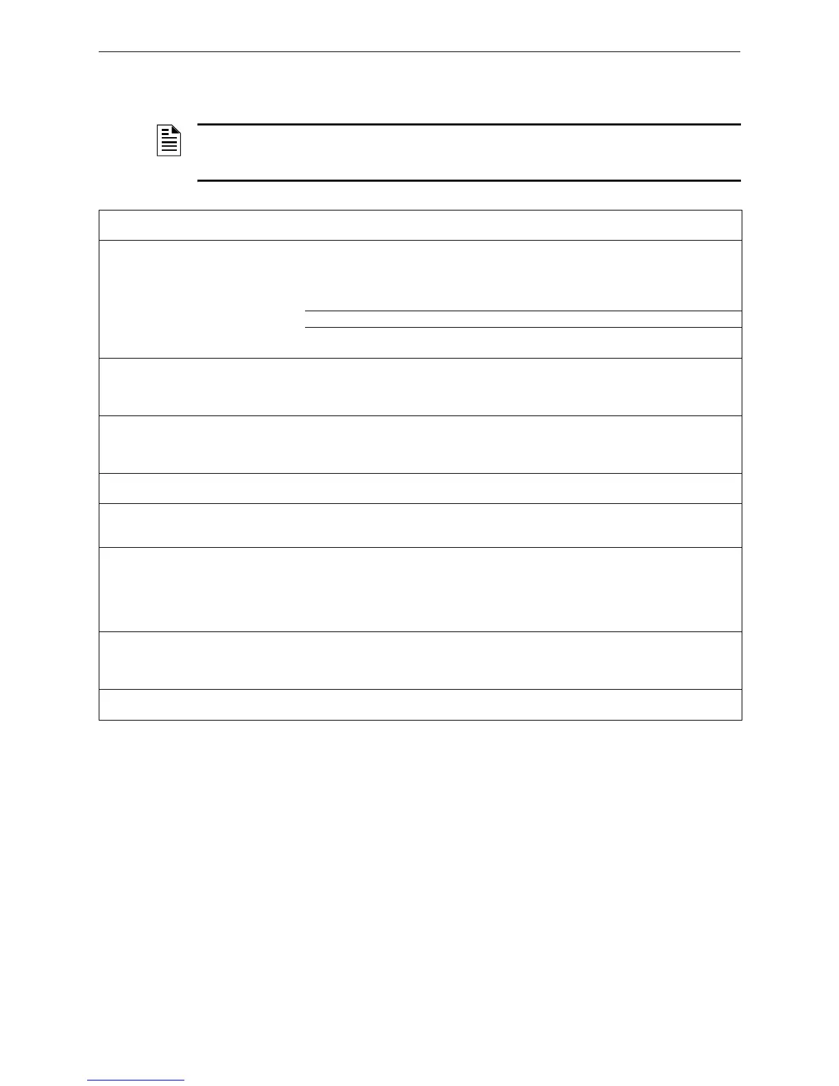
Circuit Type Circuit Function Wire Requirements
Distance
(feet/meters)
Typical Wire Type
*
SLC
(power limited)
Connects to
intelligent and
addressable
modules.
Twisted-unshielded pair, 12 to 18
AWG (3.25 to 0.75mm
2
). 50 ohms,
maximum per length of Style 6 & 7
loops. 50 ohms per branch
maximum for Style 4 loop.
12,500 ft (3,810 m)
9,500 ft. (2,895.6 m)
6,000 ft. (1,828.8 m)
3,700 ft. (1,127.76 m)
12 AWG
14 AWG
16 AWG
18 AWG
or Twisted-shielded pair. 10,000 ft (3048 m) 12 AWG
or Untwisted, unshielded wire, in
conduit or outside of conduit.
1,000 ft (304.8 m) 12 to 18 AWG
EIA-485 ACS
Connection
(power limited)
Connects to ACS
devices such as
annunciators and
UDACT
Twisted-shielded pair with a
characteristic impedance of 120
ohms. 18 AWG (0.75mm
2
)
minimum.
6,000 ft (1829 m)
(max)
16 AWG/1.30mm
2
EIA-485 RDP
Connection
(power limited)
Connects to RDP
devices such as
LCD-160
Twisted-shielded pair with a
characteristic impedance of 120
ohms. 18 AWG (0.75mm
2
)
minimum.
4,000 ft (1219 m)
(max)
16 AWG/1.30mm
2
EIA-232
(power limited)
Connects to Printers
or PC.
Twisted-shielded pair. 18 AWG
(0.75mm
2
) minimum.
50 ft (15.24 m)
without modem
16 AWG/1.30mm
2
IDC
Initiating Device
Circuit
M300MJ, M301MJ
XP5-M (power
limited)
12-18 AWG
Maximum circuit resistance is
20 ohms.
12 to 18 AWG
(3.25 to 0.75mm
2
)
NAC
Notification
Appliance
Circuit
XP5-C, M300CJ
(power limited)
12-18 AWG. MPS-24A: At alarm
current level, no more than a 1.2 V
drop at the end of the circuit, or
sized to provide the minimum rated
operating voltage of the appliances
used.
To meet 1.2 V drop, or
sized to provide the
minimum rated operating
voltage of the appliances
used.
12 to 18 AWG
(3.25 to 0.75mm
2
)
24 VDC Power
Runs
(power-limited)
To TM-4 Transmitter,
Annunciator and
M300CJ modules
12-18 AWG. Size wire so that no
more than 1.2 V drop across wire
run from supply source to end of any
branch.
To meet 1.2 volt drop 12 to 18 AWG
(3.25 to 0.75mm
2
)
CHG-120 External battery
charger
12 AWG in conduit 20 ft (6.1 m)
maximum
12 AWG
(3.25mm
2
)
Table A.1 Wire Requirements
* Notifier brand cable is recommended; see the product catalog available from Paige Electric.

 Loading...


