IFC-3030 Programming Manual — P/N 52025:C 08/05/2005 47
Point Program Program
LOCAL MODE: Press to toggle between Local Mode (ON) or no Local Mode (OFF). When there is
a communication loss between the panel and its LCM/LEMs, SLC devices that have been selected
for Local Mode participation (ON) will continue to function across all the panel’s SLCs in a limited
manner as follows: input points will activate output points of the same Type Code point type
designations. For example, SLC inputs with“fire” point types will activate SLC outputs with“fire”
point types. Refer to “Type Codes for Input Devices” on page 134 for Type Code point types.
Default: OFF
3.4.3 Panel Circuit Module
There are three panel circuits on the FACP, and each circuit can accomodate up to four panel circuit
modules that have eight push-button switches apiece. The switches can be programmed as input or
output points, depending on the module type.
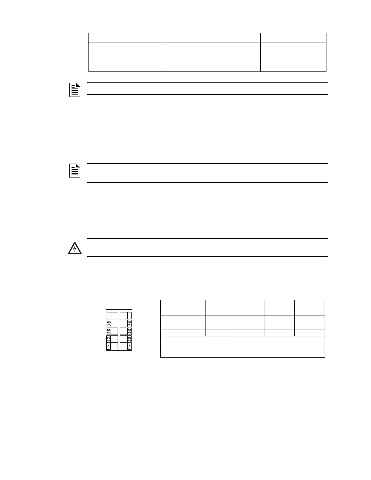
The point information is displayed onscreen in the format Pyy.z, where P means panel circuit point,
yy is the panel circuit module number (1 through 12), and z is the module push-button number (1-
8). Each panel circuit point is assigned an address by the panel depending on its location. Refer to
Figure 3.34 below for an illustration of how the panel assigns addresses.
Figure 3.34 Panel Circuit Point Addresses
YES - RESOUND SUPERV Silenceable, resound on supervisory events Network and Local Resound
YES - RESOUND SECURITY Silenceable, resound on security events Network and Local Resound
YES - RESOUND TROUBLE Silenceable, resound for trouble Local Resound
YES - NO RESOUND Silenceable, does not resound
NOTE: This soft key will not appear for modules with Type ID codes where silence is not optional.
NOTE: The panel setting LCM LOCAL MODE must be set to Yes for local mode to work at the
device level.
!
WARNING: When using alarm verification, do not mix fire alarm points with non-fire alarm
points on the same IZM-8RK/IZE-A Initiation Zone Module.
.
JCPU-3030 Panel
Circuit Connection
1st position*
module
addresses
2nd position
module
addresses
3rd position
module
addresses
4th position
module
addresses
Panel Circuit #1 (J10) P1.1 - P1.8 P2.1 - P2.8 P3.1 - P3.8 P4.1 - P4.8
Panel Circuit #2 (J11) P5.1 - P5.8 P6.1 - P6.8 P7.1 - P7.8 P8.1 - P8.8
Panel Circuit #3 (J12) P9.1 - P9.8 P10.1 - P10.8 P11.1 - P11.8 P12.1 - P12.8
* The first position is the position closest to the
JCPU-3030 connection, the fourth
position is the furthest from this connection. These address assignments are fixed; if a
panel module is not installed in position 3 of panel circuit #1, the fourth position
module still has an address of P4.yy.
Pyy.1
Pyy.2
Pyy.3
Pyy.4
Pyy.5
Pyy.8
Pyy.6
Pyy.7
Panel Circuit Module

 Loading...


