Installation—Installing the FC-2000 15
The TR-x3 Trim Ring consists of four pieces and is used when semi-flush
mounting the CAB-x3 enclosure (where x is the cabinet size, ranging
from A to D).
Note: To semi-flush mount the cabinet, ensure ample room to allow the
door to swing fully open.
1. Place the top piece on the top of the backbox against the wall.
2. Mark the wall with the locations to drill holes using the trim ring as a
template.
3. Drill 3/16 inch diameter holes where marked. Holes should be drilled
to a depth of 1 inch.
4. Insert the provided wall anchors using a rubber mallet, tapping them
in until they are flush with the wall surface.
5. Secure the trim ring piece to the wall with the screws provided.
6. Repeat Steps 1-5 to install the left, right, and bottom trim ring pieces.
Install the bottom piece last.
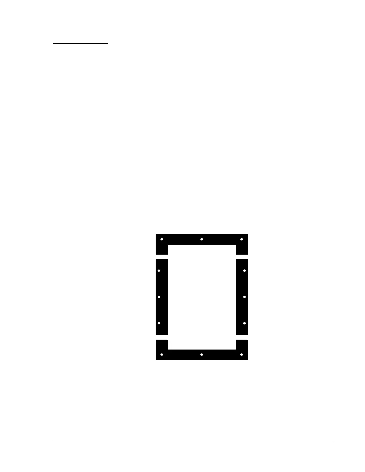
Note: The side trim ring pieces should have the holes nearest to the edge
facing outward. See Figure 6.
TR-A3 = 19-5/8 in.
TR-B3 = 28-1/8 in.
TR-C3 = 36-3/4 in.
TR-D3 = 45-3/8 in.
trimring
Figure 6: Trim Ring Installation
Trim Ring for
CAB-x3
Enclosures
Installing the
Trim Ring
 Loading...

