Installation—Installing the FC-2000 39
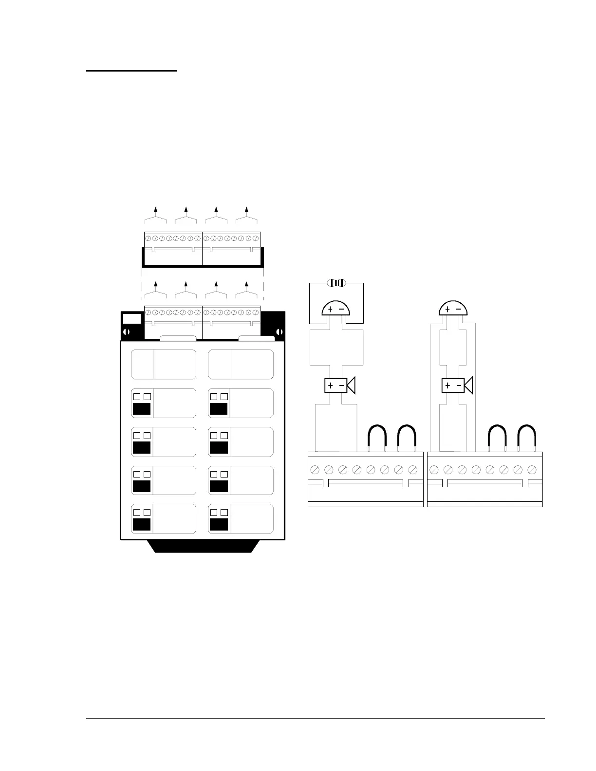
Figure 28: NFPA Style Y, Z Field Wiring of Indicating Circuit Module (ICM-4)
and Expander (ICE-4)
Notes:
1. Indicating appliance circuits are supervised, power limited, and may
be connected to energy-limited cable.
2. Use only the compatible, UL Listed indicating appliances listed in
Device Compatibility document in the Fire Management Accessories
Manual (FAN 445).
Typical NFPA
Style Y and Z
Indicating
Appliance
Circuit
nfpa-y-z
1 2 3 4 5 6 7 8
B+ A+ A- B- B+ A+ A- B-
4.7K, 1/2 watt ELR.
Part No. 71252 (Note 5).
UL Listed
24 VDC
Polarized Bell
UL Listed
24 VDC
Polarized
Horn
1 2 3 4 5 6 7 8
B+ A+ A- B- B+ A+ A- B-
Jumper
unused
circuits.
Jumper
unused
circuits.
A
E
B
F
CG
DH
INITIATING
CIRC UIT
GREEN - ON
YE LLOW - TRO UBLE
ON / OFF
MODULE
TYPE
LAM PS
SWITCH
INITIATING
CIRCUIT
GREEN - ON
YELLO W - TR OUBLE
ON / OFF
MODULE
TYPE
LAM PS
SWITCH
b+a+ a-b- b+a+ a- b-
E F G H
b+a+ a-b- b+a+ a- b-
ICB
b+a+ a-b- b+a+ a- b-
A B C D
b+a+ a-b- b+a+ a- b-
Typical NFPA Style Y
Indicating Appliance
Circuit
Typical NFPA Style Z
Indicating Appliance
Circuit
Optional ICE-4 Indicating Circuit Expander.
Positions E, F, G, and H are active only with
this board installed. Note that CRE-4
expander may also be installed on the ICM-4.
 Loading...

