54 Installation—Installing the FC-2000
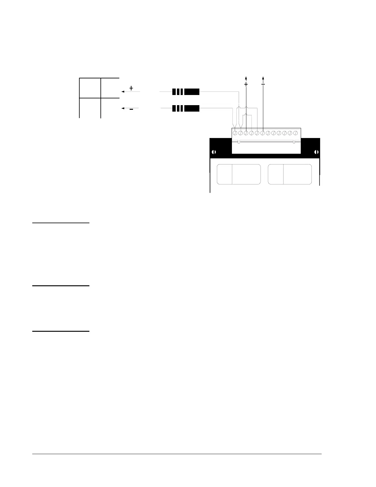
Figure 38: Supervisory Remote Station Output Signal
The control panel can be employed as a Central Station Premise Control
Unit when used in conjunction with a compatible, UL Listed Electrically
Activated Transmitter installed in accordance with the Transmitters
section (below) of this document or when used in conjunction with a
compatible, UL listed Digital Alarm Communicator installed in
accordance with the Digital Communicators section of this document.
The control panel can be employed as a Central Station Premise Control
Unit when used in conjunction with a compatible, UL listed Electrically
Activated Transmitter installed in accordance with the instructions given
in the Transmitters section of this document.
Electronically actuated transmitters can be used with the control panel to
form Central Station and Proprietary Protective Signaling Systems
provided that the following conditions are satisfied:
1. The control unit is used with the NIB-96 transmitter.
2. The receiving unit is the IFC-1010/2020.
3. The transmitters are installed according to their instructions in the
NIB-96 Network Interface Board Technical Bulletin in the Fire
Management Accessories Manual (FAN 445).
4. The controller, transmitters, and receivers must have a standby power
source that can supply 24 hours of operating power.
CONTROL
RELAY
GREEN - ON
YELLOW- TROUBLE
ON/OFF
MODULE
TYPE
LAMPS
SWITCH
CONTROL
RELAY
GREEN - ON
YELLOW- TROUBLE
ON/OFF
MODULE
TYPE
LAMPS
SWITCH
1 2 3 4 5 6 7 8 9 10 11 12
crm4wire
Cable Assembly 71270
(680-ohm, 1-watt current limiting resistors)
MPS-24A MPS-24B
TB3 (1)
TB3 (2)
TB2 (1)
TB2 (2)
Red Wire
Black Wire
Remote Station Output Signal
Intended for connection to a polarity
reversal circuit of a remote station
receiving unit having compatible
ratings. The normal standby polarity
is shown.
CRM-4 or CRE-4
Central Station
Proprietary
Protective
Signaling
Transmitters
 Loading...

