Installation—Installing the FC-2000 41
Power Supplies
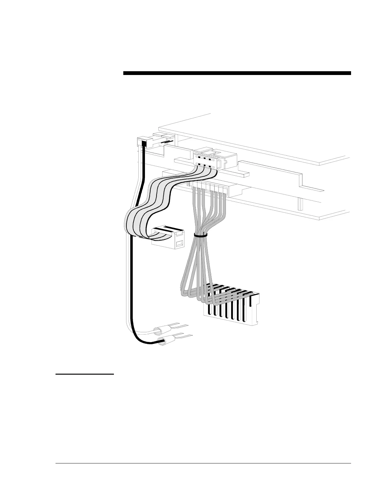
Three cables complete the electrical connection between the CPU and the
main power supply.
Figure 30: Cable Connection Example
The MPS-24A Main Power Supply is an optional supply capable of
powering the control panel continuously during standby and alarm
conditions. A total of 3.0 amps (internal) @ 24 VDC regulated is
available from the main power supply for operating the system during
standby conditions. No more than 6 amps @ 24 VDC can be drawn from
the MPS-24A during alarm.
Figures 31 and 32 illustrate connections for primary and secondary power
to the MPS-24A Main Power Supply, as well as terminal and harness
connections for the system.
3cablcon
MPS Bell
Power
Harness
(71093)
Blue to Bell Power (+)
Black to Bell Power (-)
Power
Ribbon
(75185)
Connect to P3
on the MPS-24A/B.
Main Power Harness
(71086)
Connect to P2
on the MPS-24A/B.
CPU
(Bottom View)
MPS-24A Main
Power Supply
 Loading...

