12 Installation—Installing the FC-2000
14. Programming--To configure and program the system for operation, refer
to the Programming the FC-2000 Technical Bulletin in this manual.
15. Batteries--Once the system has been programmed and is functional,
connect the batteries. Ensure that all indicators except AC POWER
are extinguished.
16. Testing--Fully field test the system by conducting the test procedure
in the Testing the System section of this document.
17. Dress Panels--Complete the installation by installing the cabinet door
first, followed by the Battery Dress Panel (BP-3), and finally,
installing all remaining dress panels (VP-1, DP-1, and the MP-1).
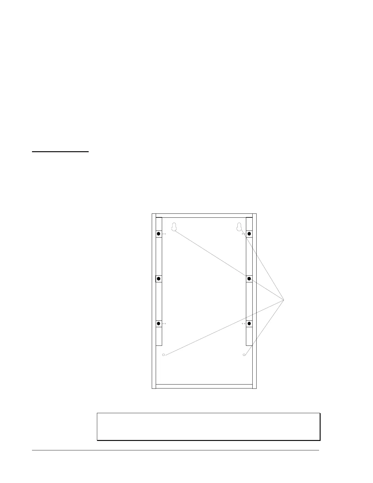
● You may either surface or semi-flush mount the cabinet.
● Mount the cabinet in a clean, dry, vibration-free area, using the four
holes provided in the back surface of the backbox.
● Place the cabinet so that the top edge is 66 inches above the surface of
the finished floor. This procedure places the center of the control
panel keypad 60 inches above the finished floor.
CAB-C3
Mounting
Holes
bckbxmnt
Note: The lock for this
cabinet is mounted
on either the left or the
right side. Leave
3 inches clearance on
the side of the
backbox where the
lock is located.
Figure 3: Mounting the Cabinet Backbox
IMPORTANT: Unless you are familiar with the placement of
components within this backbox, use only the knockout
locations provided for conduit entry.
Cabinet
Installation
Mounting the
CAB-x3 Cabinet
Backbox
 Loading...

