60 Installation—Installing the FC-2000
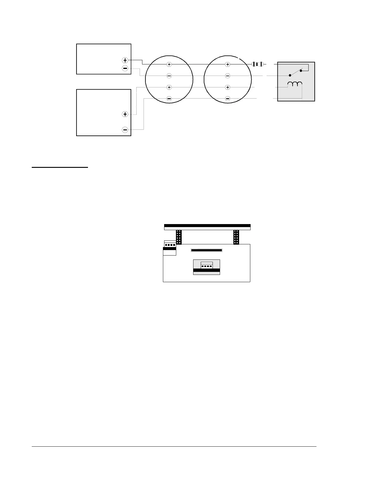
Figure 43: Employing 4-Wire Smoke Detectors (Style B)
The total current available from any group of indication appliance circuits
cannot exceed 3.0 amps. Figures 45 and 46 illustrate some of the typical
power supply/indicating appliance circuit configurations.
Note: The term “total” in these figures assumes that no indicating
appliance power is drawn for any other purpose.
J5 J6
ICM-4
ICE-4
botmicm4
Figure 44: Bottom Wire of the ICM-4/ICE-4
wire-b
IZM-8
Initiating Device
Circuit
MPS-24A
TB3 Term 1(+), 2(-)
24 VDC
4-Wire Detector Power
MPS-24B
TB2 Term 1(+), 2(-)
UL Listed 24 VDC
4-Wire Smoke Detectors
UL Listed
Power Supervision
Relay
C
+24 VDC
-0 VDC
NC
4.7K, 1/2-watt ELR
Part No. 71245
IDC(+)
IDC(-)
24 VDC(+)
Common
IDC(+)
IDC(-)
24 VDC(+)
Common
Indicating
Appliance
Circuit Current
Limitations
 Loading...

