EasyManuals Logo

Johnson Controls MPS-24A Installing Instruction

Johnson Controls MPS-24A
84 pages
To Next Page IconTo Next Page
To Previous Page IconTo Previous Page
Page #61 background imageLoading...
Page #61 background image
Installation—Installing the FC-2000 61
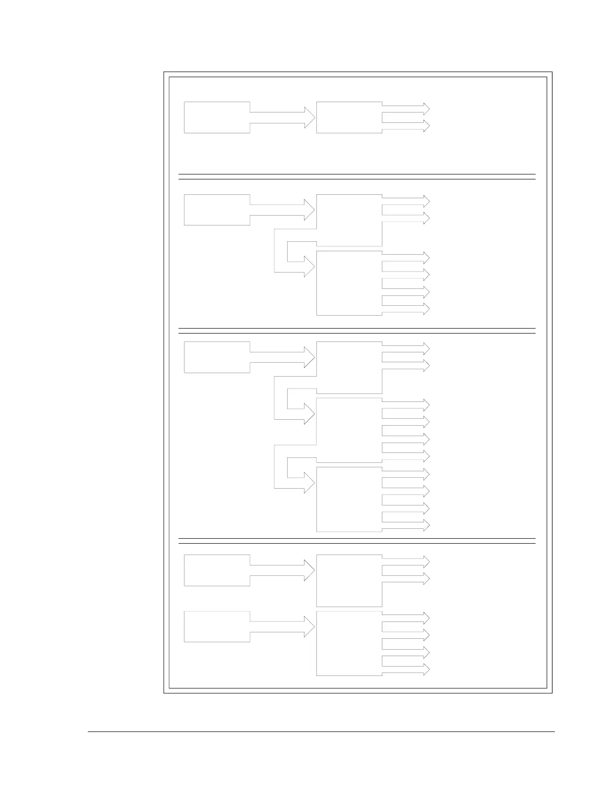
Figure 45: Typical Supply/Indicating Appliance Circuit Configurations
circonfg
MPS
These two indicating
appliance circuits share the
total MPS current.
J5
CPU
Module
MPS
These six indicating
appliance circuits share the
total MPS current.
J5
CPU
Module
J5
ICM-4
J6
MPS
These ten indicating
appliance circuits share the
total MPS current.
J5
CPU
Module
J5
ICM-4
J6
J5
ICE-4
J6
MPS
These two indicating
appliance circuits share the
total MPS current.
J5
CPU
Module
J5
ICM-4
AVPS-24
J6
These four indicating
appliance circuits share the
total 3 amps of current on
the AVPS-24.

Table of Contents

Other manuals for Johnson Controls MPS-24A

Questions and Answers:

Question and Answer IconNeed help?

Do you have a question about the Johnson Controls MPS-24A and is the answer not in the manual?

Johnson Controls MPS-24A Specifications

General IconGeneral
BrandJohnson Controls
ModelMPS-24A
CategoryControl Panel
LanguageEnglish

Related product manuals