62 Installation—Installing the FC-2000
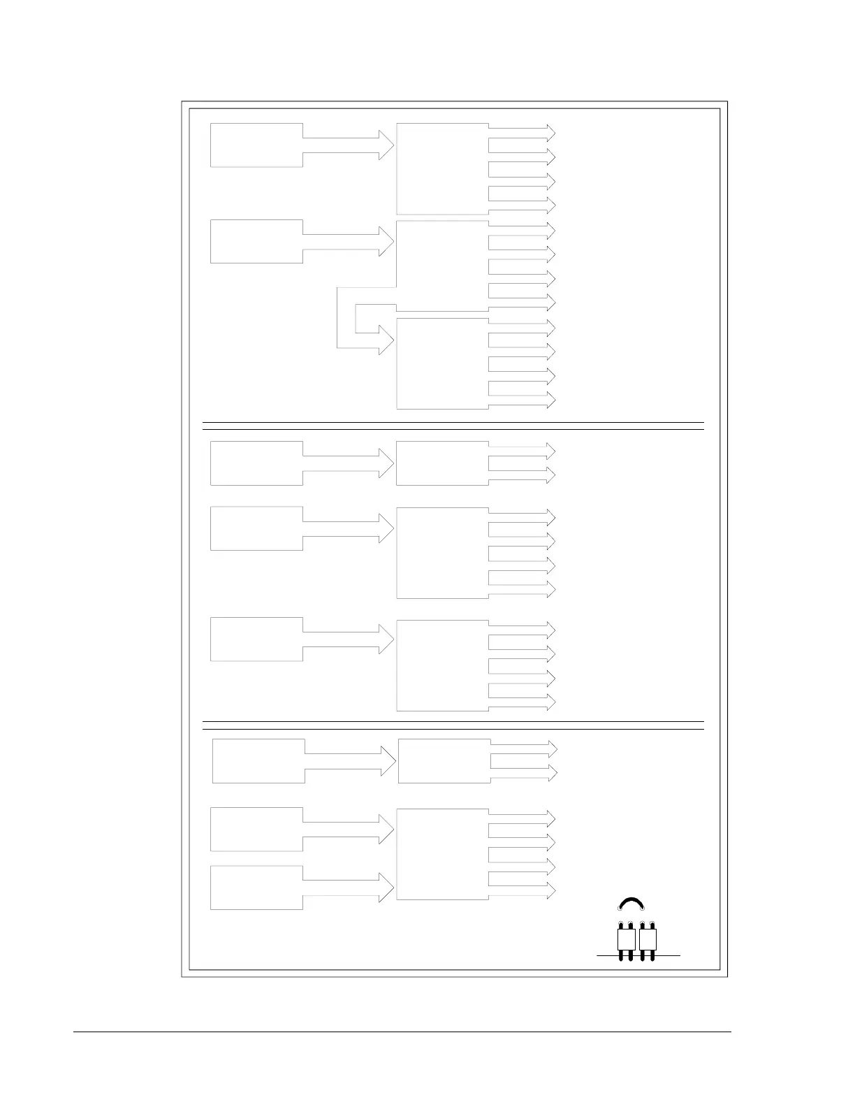
Figure 46: More Typical Supply/Indicating Appliance Circuit Configurations
circong2
These two indicating
appliance circuits share the
total MPS current.
J5
ICM-4
J5
ICE-4
J5
ICM-4
AVPS-24
These four indicating
appliance circuits share 3.0
amps of one AVPS-24.
J5
ICM-4
J6
J5
ICE-4
J5
ICM-4
AVPS-24
AVPS-24
MPS
J5
CPU
Module
AVPS-24
AVPS-24
These four indicating
appliance circuits share 3.0
amps of one AVPS-24.
MPS
J5
CPU
Module
AVPS-24
J6
For this particular configuation (using two
AVPS-24 supplies to power an ICM-4 or ICE-4),
cut jumper JP1 located above J5 and J6.
JP1
J5 J6
These eight indicating
appliance circuits share 3.0
amps of the second
AVPS-24.
These four indicating
appliance circuits share 3.0
amps of one AVPS-24.
These two indicating
appliance circuits share the
total MPS current.
These two circuits share
3.0 amps of one AVPS-24.
These two circuits share
3.0 amps of one AVPS-24.
 Loading...

