Installation—Installing the FC-2000 35
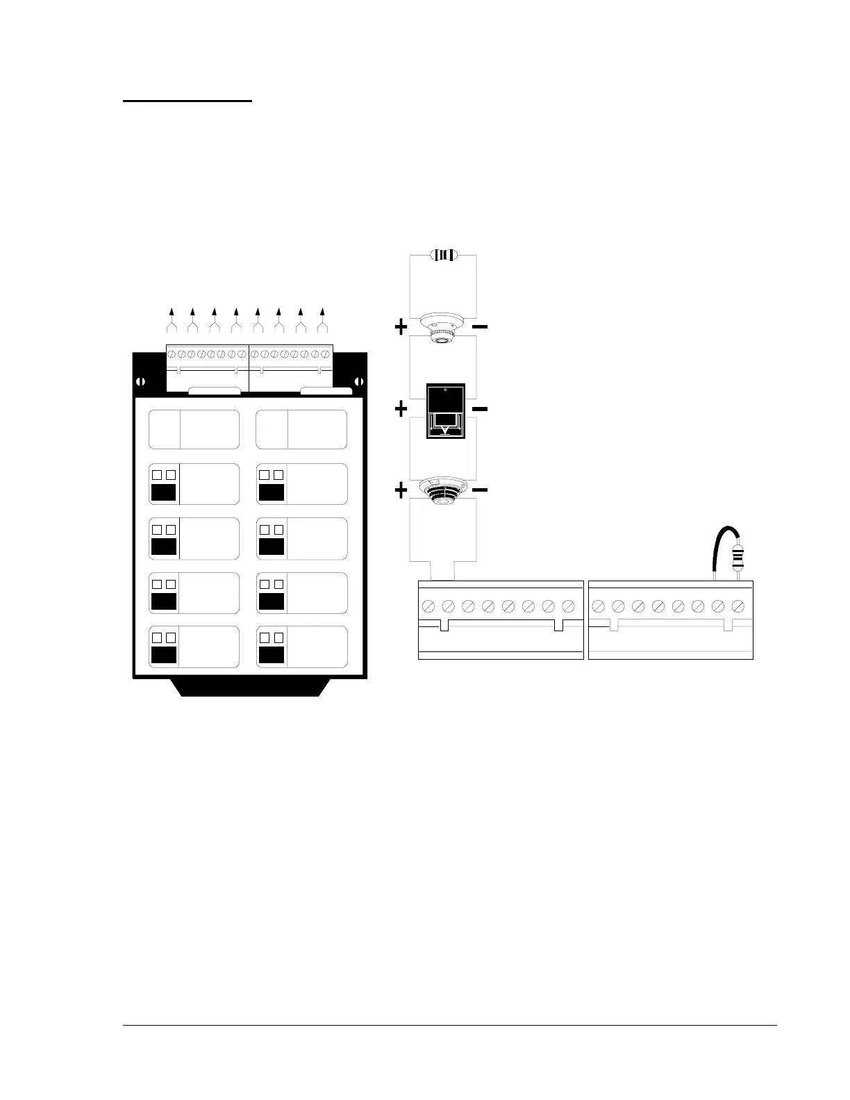
Figure 26: NFPA Style B Field Wiring of the IZM-8 Initiating Zone Module
Notes:
1. Initiating device circuits are supervised, power limited, and may be
connected to limited-energy cable. Initiating devices include
non-coded manual pull stations, heat detectors, photo and ion
detectors, and waterflow alarm and waterflow supervisory devices.
Connect waterflow alarm devices to a dedicated circuit programmed
for the waterflow option. Connect N.O. waterflow supervisory
devices to a dedicated zone programmed for supervisory operation.
Terminal Block will accept 12 to 22 AWG wire. Initiating circuit
current will ensure alarming of one 2-wire detector only.
Typical NFPA
Style B Initiating
Device Circuit
IZB
b+b- b+b- b+b- b+b-
A B C D E F G H
b+b- b+b- b+b- b+b-
nfpa-b
4.7K, 1/2 watt ELR, Part No. 71252 (Note 5).
Dummy load all
unused circuits with
4.7K, ELR,
Part No. 71245.
1 2 3 4 5 6 7 8
B+ B-
1 2 3 4 5 6 7 8
B+ B-
UL Listed 2-wire Smoke Detector (Note 2)
Manual Pull Station
Heat Detector
Typical NFPA Style B
Initiating Device Circuit
PUS H IN
THEN
PULL DOW N
FIRE
A
INITIATING
ZONE
RED-ALARM
YELLO W- TRO UBLE
DISPL AY PRO GRAM
MODULE
TYPE
LAMPS
SWITCH
INITIATING
ZONE
RED-ALARM
YELLO W- TRO UBLE
DISPL AY PRO GRAM
MODULE
TYPE
LAMPS
SWITCH
E
B
F
C
G
D
H
 Loading...

