Installation—Installing the FC-2000 57
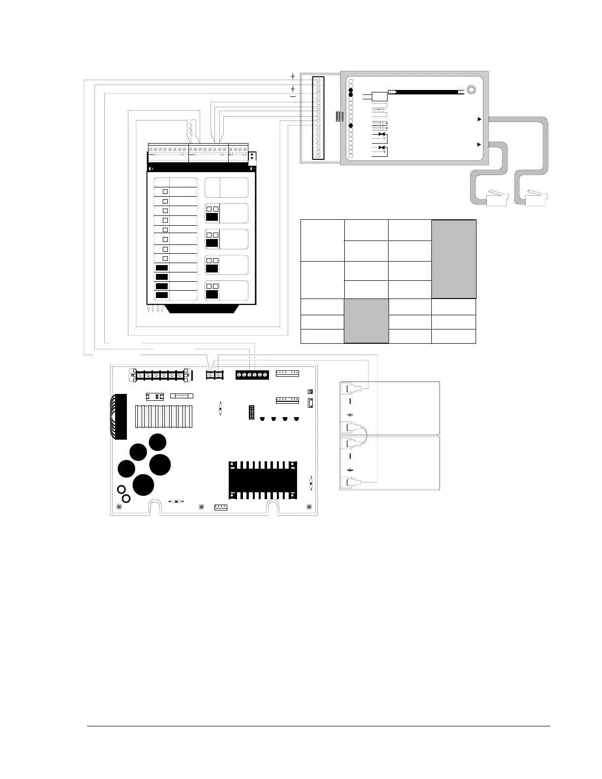
Figure 40: Connection of a 911A Digital Communicator
Note: For supervisory contacts, program the initiating zone(s) and map
the output to the supervisory contacts. Set zone 2/3 in DACT for
Mode 3.
P3
P2
P4
P5
P6
JP5
P7
JP1
JP2
TB1
CB1
P1
1 2 3 4 5 6 7 8
1 2 3 4 5 6
1 2
911A
Digital A larm Comm unic at or Lis ted for Ce ntra l Station or Rem ote S tation S erv ice
Slide C ov er Bac k to A ccess Pro gramming Jack and Relays
Phone Fail LED
Alternate RJ31X
Telco Jack
Primary RJ31X
Telco Jack
12 VA C 20 VA , 6 0 Hz or +2 4 V DC
12 VA C 20 VA , 6 0 Hz or -2 4 V DC
Refer to 911A Manual
Battery -
Battery +
Iniating A1-
Iniating A2-
Iniating B1+
Iniating B2+
Supervisory HI
Supervisory LO
Supervisory HI
1
2
5
6
7
8
9
12 VDC Sealed
Rechargeable
Battery
3
4
11
10
12
13
14
Trouble Relay NC
Trouble Relay CO M
15
Trouble R ela y NO
Alarm Relay NC
Alarm Relay COM
Alarm Relay NO
16
17
18
1
2
3
4
5
6
7
8
9
10
11
12
13
14
15
16
17
18
conn911a
INDICATING
CIRC UIT 1
INDICATING
CIRC UIT 2
XXXXXX
XXXXX
MUNICIPAL
XX
ALARM
RELAY
1 2 3 4 5 6 7 8
9 10 11 12 13 14 15 16
17 18 19 20
J11
SPEAKER
CIRCUITS
GREEN - ON
YELLOW- TROUBLE
ON/OFF
MODULE
TYPE
LAMPS
SWITCH
DISABLE
UNABLE
DISABLE
UNABLE
DISABLE
UNABLE
DISABLE
UNABLE
DISABLE
UNABLE
DISABLE
UNABLE
DISABLE
UNABLE
DISABLE
UNABLE
DISABLE
UNABLE
DISABLE
UNABLE
DISABLE
UNABLE
DISABLE
UNABLE
SYSTEM
6000
FIRE
ALARM
MPS-24A
CPU
911A
Trouble Alarm
To
Central
Station
Common
(+) 24 VDC
(+) 27.6 VDC
Alarm
normally
open
contacts
CPU 911A MPS
Trouble
normally
open
contacts
+ 24 VDC
Common
+ 27.6 VDC
TB1-14
TB1-15
TB1-9
TB1-11
6 and 7
8 and 9
10
11
2
4
1
TB3-3
TB3-4
TB2-1
 Loading...

