Installation—Installing the FC-2000 69
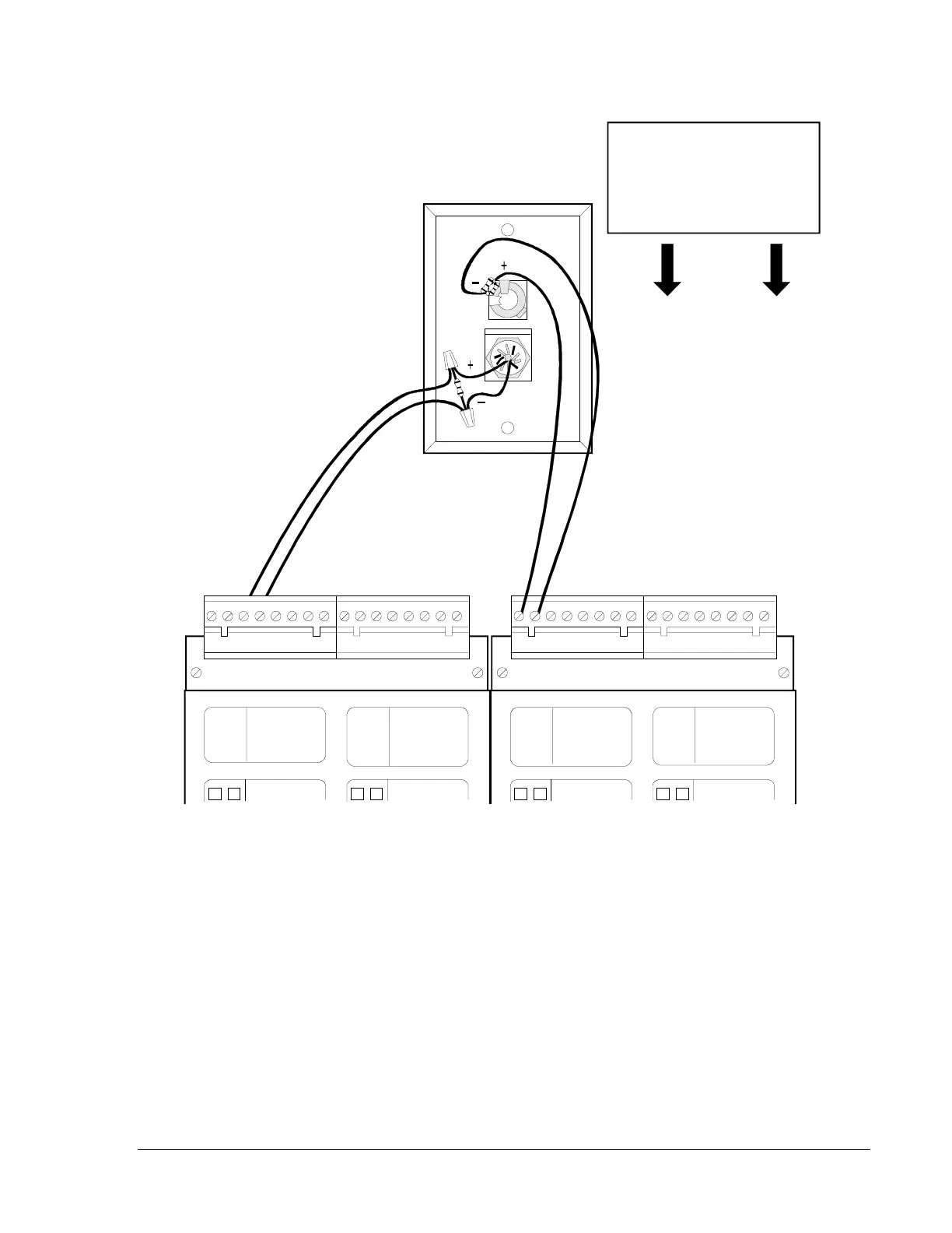
Figure 52: Connection Diagram for Telephone Page
conntele
RPJ-1 (Back)
Remote Page Circuit
Black (-), Red (+)
Wire nut an R-4.7K ELR
across the Key Switch Circuit.
Do not cut resistors
on Phone Jack input.
To 24 VDC
Power
To RS-485
Port
IZM-8 VCM-4
ACM-16AT/AEM-16AT Annunciator
with AKS-1:
Set Receive/Transmit operation
mode (set switch SW5 OFF).
Telephone Page Connections
For All Call operation, connect key switch
to IZM-8 circuit "C."
Note: An annunciator is not required for
All-Call service.
+ - + - + - + -
A B C D E F G H
+ - + - + - + -
MODULE
TYPE
LAMPS
SWITCH
INITIATING
ZONE
RED -ALARM
YELLOW - TROUBLE
DISPLAY PROGRAM
INITIATING
ZONE
RED -ALARM
YELLOW - TROUBLE
DISPLAY PROGRAM
+ - + - + - + -
A B C D E F G H
+ - + - + - + -
TELEPHONE
CIRCUIT
RED - CALL
YELLOW - TROUBLE
ON/OFF
TELEPHONE
CIRCUIT
RED - CALL
YELLOW - TROUBLE
ON/OFF
MODULE
TYPE
LAMPS
SWITCH
MODULE
TYPE
LAMPS
SWITCH
MODULE
TYPE
LAMPS
SWITCH
 Loading...

