78 Installation—Installing the FC-2000
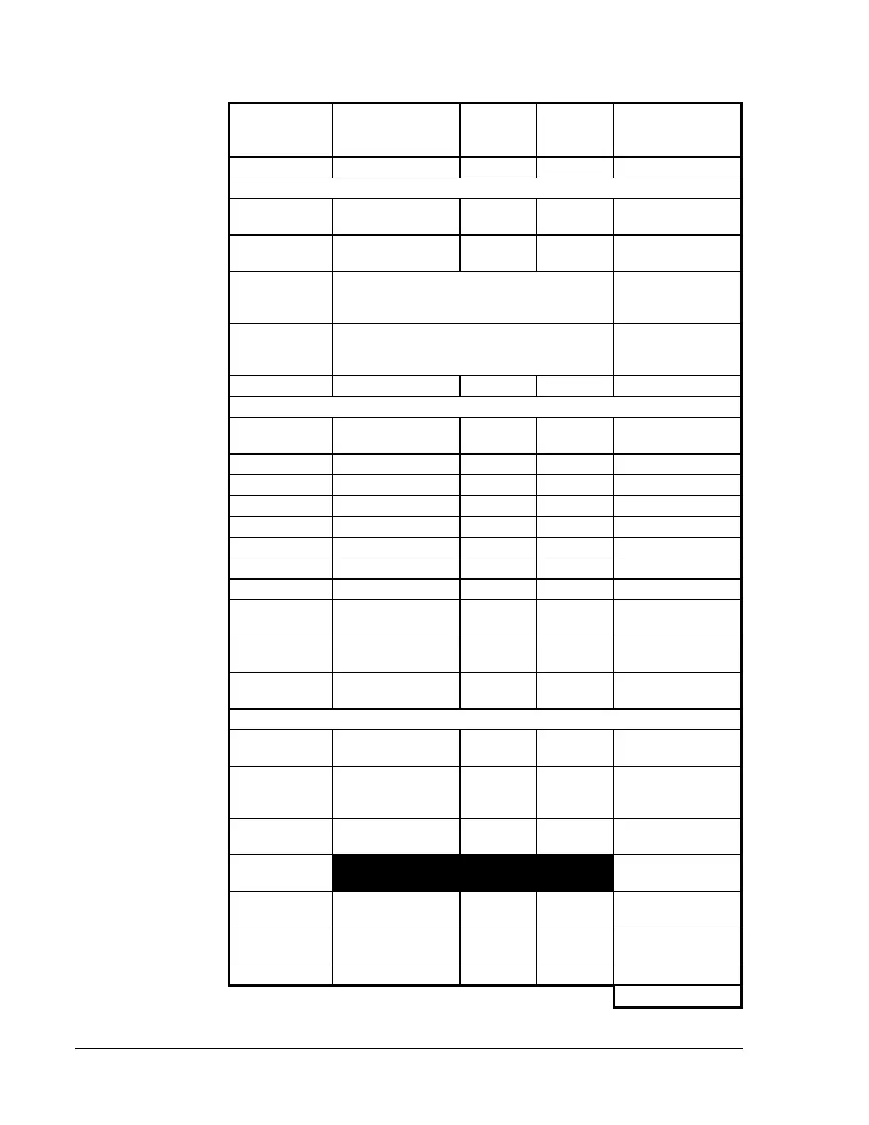
Device Type
(Cont.)
Number of
Devices in Alarm
Simultaneously
Multiply
By
Current
in Amps
Total
Current/Device
FFT-7, FFT-7S
[ ] X 0.095
RS-485 Modules
ACM-16AT,
ACM-32A
[ ] X 0.056
AEM-16AT,
AEM-32A
[ ] X 0.018
LDM Series
Annunciators
Use Alarm total from
LDM-32
Lamp Driver
Modules Technical Bulletin
in the
Fire
Management Accessories Manual (FAN 445).
ACM-8R
Use Alarm total from
ACM-8R
Annunciator
Control Module Technical Bulletin
in the
Fire
Management Accessories Manual (FAN 445).
LCD-80
[ ] X 0.100
Initiating Circuit Loading (refer to Note 3)
2-Wire Smoke
Detectors
[] X (Alarm
Draw)
1 to 30 zones
[ ] X 0.120
31 to 40 zones
[ ] X 0.160
41 to 50 zones
[ ] X 0.200
51 to 60 zones
[ ] X 0.240
61 to 70 zones
[ ] X 0.280
71 to 80 zones
[ ] X 0.320
81 to 90 zones
[ ] X 0.360
91 to 100
zones
[ ] X 0.400
101 to 110
zones
[ ] X 0.440
111 to 120
zones
[ ] X 0.480
External Circuits Draw (refer to Notes 1 and 2):
4-Wire Smoke
Detectors
[] X (Alarm
Draw)
Power
Supervision
Relays
[] X []
Remote
Station Circuit
[ ] X 0.018
TCM-2/TCM-4
Circuits
Releasing
Device Draw
[] X []
Indicating
Appliances
[] X (Alarm
Draw)
911A [ ] X 0.030
Sum Column for Alarm State Regulator = amps
 Loading...

