82 Installation—Installing the FC-2000
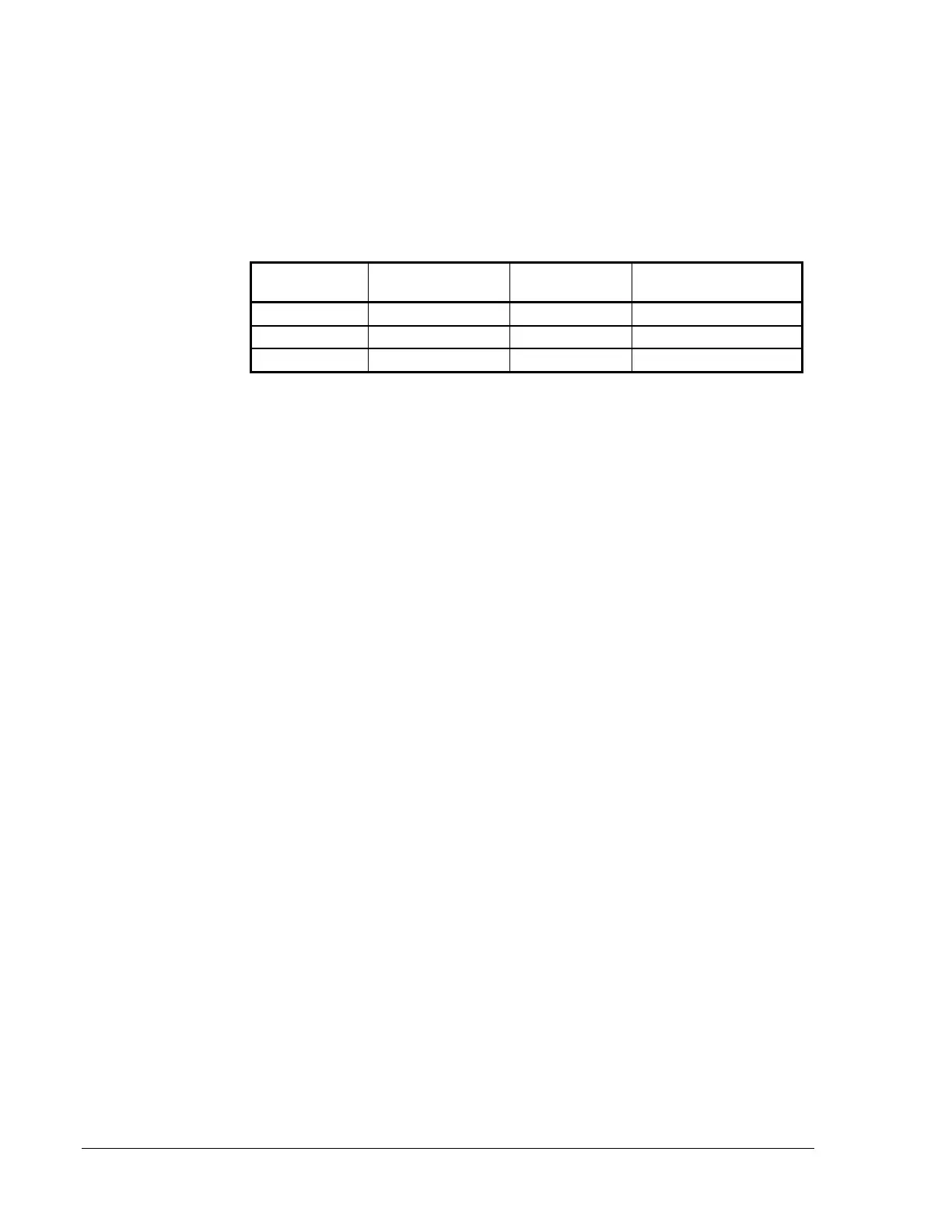
Table 6 sums the standby and alarm loads to arrive at the battery size, in
amp hours, needed to support the system. Each MPS-24A/MPS-24B has a
specific range of batteries that can be charged properly. Select batteries
that meet or exceed the total amp hours calculated and the are within the
acceptable charger range.
Table 7: Calculating Necessary Battery Size
System
Requirement
Total Load
(During Alarm)
Number
Required
Model Number
23 or less AH 9 amps or less 2 JC12250
23-55 AH 9-20 amps 2 GC12550
56 or more AH 21 amps or more UPS required UPS required
Battery Charger Amp Hour Range
MPS-24A: (9-25 AH)
MPS-24B: (6.5-17 AH)
NR45-24: (20-55 AH)
Calculating
Battery Size
Needed
 Loading...