FORM 160.77-O2
ISSUE DATE: 11/15/2011
SECTION 5 - DISPLAY MESSAGES
JOHNSON CONTROLS
123
5
Pri VSD Fault: High Phase X Inverter
Baseplate Temp
The unit will contain three heatsink assemblies within
the three inverter power phase bank assemblies. The
heatsinks willwill each contain a single Klixon® tem-
perature sensor. All inverter heatsink temperatures are
compared to a prescribed limit of 175°F (+/- 7°F) 79°C
(+/-4°C) .
If this limit is exceeded the unit will initiate a safety
shutdown and the control panel will display the mes-
sage “PRI VSD FAULT: HIGH PHASE X INVERTER
BASEPLATE TEMPERATURE”, where X is either A,
B or C corresponding to the power device connected to
output terminals T1, T2 and T3 respectively. The units
Klixons® resets when all inverter heatsink tempera-
tures fall below their reset limit of 145°F (+/- 10°F)
63°C (+/-5.5°C). In order to initiate restart, the control
panel’s reset button must be pressed.
Pri VSD Fault: High Instantaneous Current
Two of the three output lines (T1 & T3) to the motor are
continuously monitored via two DC current transform-
ers within the drive. The third phase (T2) is derived.
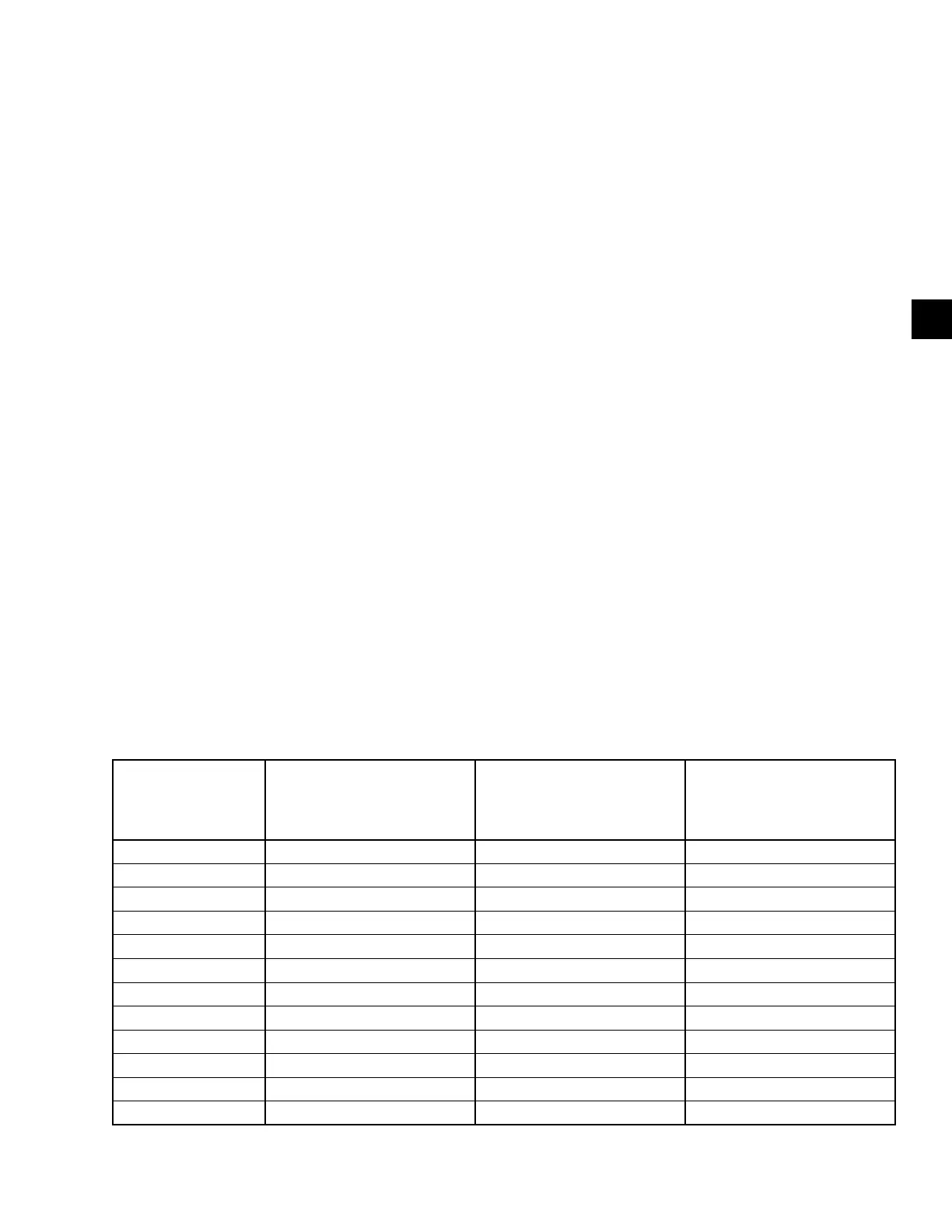
The unit’s three phases of instantaneous output current
are continuously compared to an instantaneous limit of
233% of the drive’s 100% FLA rating (see the follow-
ing table). If this peak instantaneous current trip limit
is exceeded, the unit will initiate a shutdown and the
control panel displays the message “PRI VSD FAULT:
HIGH INSTANTANEOUS CURRENT”.
HP RATING
Peak Instantaneous
Motor Over current Trip
2300 Volt 60Hz Model
Peak Instantaneous
Motor Over current Trip
3300 Volt 50/60Hz Models
Peak Instantaneous
Motor Over current Trip
4160 Volt 60Hz
6600 Volt 50/60Hz Models
500 250 182 145
600 301 219 173
700 366 257 203
800 401 292 231
900 471 329 261
1000 523 364 289
1250 653 455 362
1500 784 548 434
1750 915 639 506
2000 1022 728 579
2250 1153 805 639
2500 1309 912 723
TABLE 7 - OVER-CURRENT TRIP
Pri VSD Fault: Gate Driver XYZ
The unit contains three inverter power poles, one per
output phase. Each inverter power contains IGBT gate
driver control boards. These boards monitor the satu-
ration voltage appearing across IGBT’s #1 & #5 (two
upper most in the cell) and #4 & #8 (two lower most
in the cell) while gated on, and the isolated gate driver
power supply. If the IGBT’s saturation voltage exceeds
a prescribed limit, the gate driver will make the deter-
mination that a short circuit is present. This in turn will
cause the unit to initiate a shutdown.
In addition, if the isolated power supply level falls be-
low a predetermined limit a cycling shutdown will be
initiated. The control panel will display the message
“PRI VSD FAULT: GATE DRIVER XYZ”, where X
is either A, B or C corresponding to the unit’s inverter
power cell connection to output terminals T1, T2 and
T3 respectively, Y denotes the location of the IGBT in
the pole in relation to its connection, either to the inter-
nal neutral connection of the poles or to the motor ter-
minal (N, neutral, indicates connection to the neutral,
M, motor, indicates connection to the motor terminal)
and Z denotes the location of the device relative to the
internal neutral connection (U, upper - #1 or #5 or L,
lower - #4 or #8).

 Loading...


