106
The measuring position is shown as the
figure,
5. Assembling of the crankshaft connecting rod mechanism
5.1. Assembly of the piston and connecting rod
5.1.1. Use special tools to assemble the
piston, connecting rod and piston
pin in the following specified
procedures.
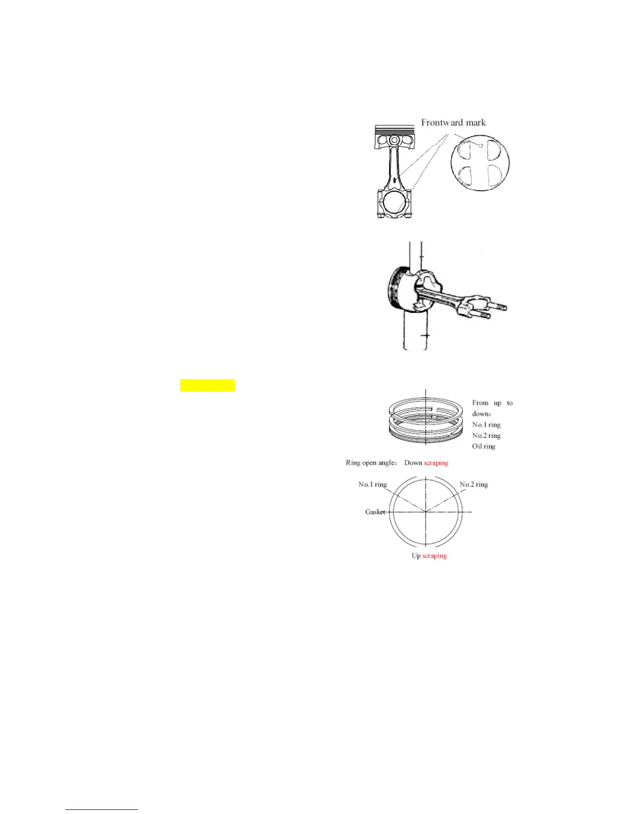
5.1.1.1. Smear lubricating oil to the
connecting rod pin hole, and make
the assembly according to the
marks for the same unit and in the
indicated direction.
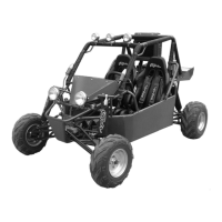
5.1.1.2. Make the installation shown as the
right figure.
5.1.1.3. Make adjustments and installation
of the piston and the connecting
rod shown as the right figure. After
smearing lubricating oil to the
piston pin, use pressurizing device
to assemble the piston and the
connecting rod.
Attention
· Pay attention to the assembling direction
when pressing in the piston pin;
The small bit of connecting rod should be
heated to 300℃/572℉ while pressing the
piston pin in the piston. Exert pressure in
the process of pressing to assure the
alignment of the pin.
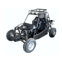
5.2. Install Primary ring, the secondary
ring and the oil ring in the following
specified procedures.
5.2.1. Install gas ring
Side face with marks should be upright,
install primary ring with piston ring tool.
5.2.2. Install oil ring (gasket ring, down
scraper and upper scraper) firstly,
then install the secondary ring, then
install the primary ring, Open
degree of every ring is shown as the
illustration: