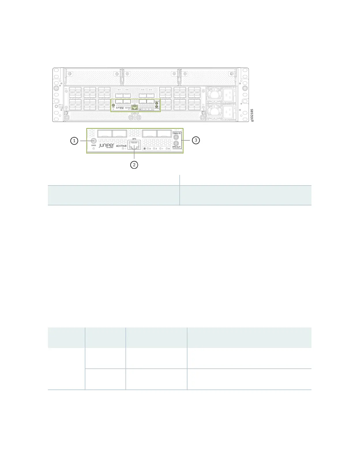
Figure 5: Timing Interface Ports
1—
GNSS port
3—
10MHz (I/O), 1PPS (OUT) port
2—
BITS—Building-integrated ming supply
(BITS) port
Here's a denion of the ports and labels on the ming interface ports. See Table 4 on page 14 for a
descripon of the ming ports LED indicators.
• GNSS antenna port—Connects to a GNSS antenna.
• BITS—Building-integrated ming supply (BITS) external clocking interface for connecng to external
clocking devices.
• 10MHz (I/O)—10-MHz input and output clocking port for connecng to external clock signal
sources. The clocking port synchronizes clock inputs based on the clock’s priority.
• PPS—1-pulse per second (PPS) output connector for connecng to external clock signal sources. The
clocking port synchronizes clock inputs based on the clock’s priority.
Table 4: Timing Ports LEDs on the ACX7348 Chassis
LED Color State Descripon
GNSS Unlit O GNSS signal is not locked.
Green On steadily GNSS signal is locked.
14