The low-speed bundle receives network-bound clock and data signals from the user
equipment and inserts it into the bundle. It also transmits interface-bound clock and
data from the bundle to the user equipment.
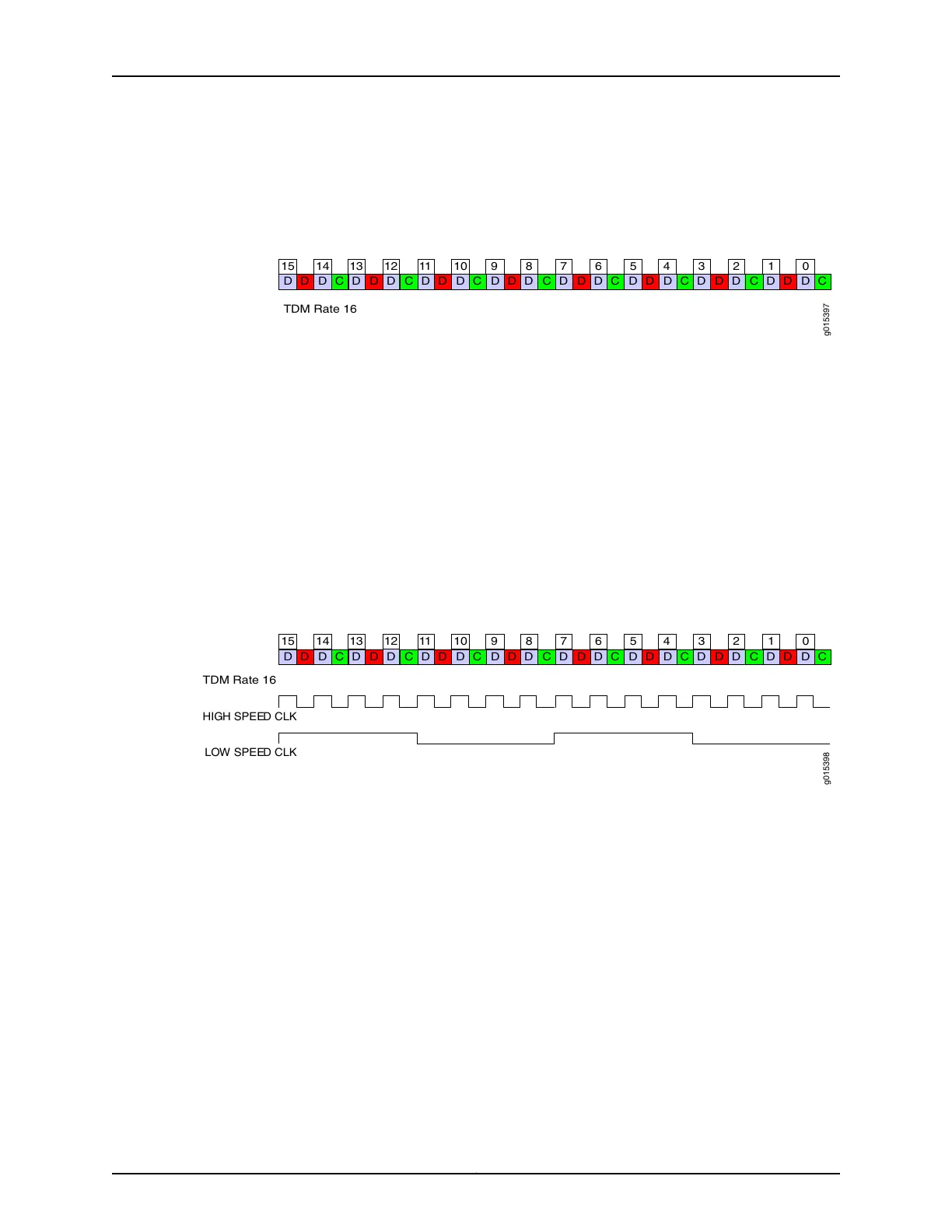
Figure 11: TDC Application Over TDM Using 16-in-32 TDM Rate
g015397
D D CD D D D D D D D D D D D D D DD C D C D C D C D C D C D C
012345678911 1013 1215 14
TDM Rate 16
In Figure 4:
•
The blue D bits synchronously carry the higher-speed circuit.
•
The red D bits asynchronously oversample and transport the lower-speed circuit data.
•
The green C bits asynchronously oversample and transport the lower-speed circuit
clock.
TDM Rates
At the maximum TDM rate of 16, the CTP device can transport four low-speed bits for
every eight high-speed bits as shown in Figure 12 on page 19.
Figure 12: High-Speed and Low-Speed Ratio at the Maximum TDM Rate
of 16
g015398
D D CD D D D D D D D D D D D D D DD C D C D C D C D C D C D C
012345678911 1013 1215 14
HIGH SPEED C LK
LOW SPEED CLK
TDM Rate 16
If the ratio of circuit speeds is higher than 8:1, then you can use lower TDM rates, which
allocates fewer bits for the TDM function and therefore uses less network bandwidth.
Figure 13 on page 20 shows other supported TDM rates as applied to TDC.
19Copyright © 2018, Juniper Networks, Inc.
Chapter 1: Overview of CTP Bundles