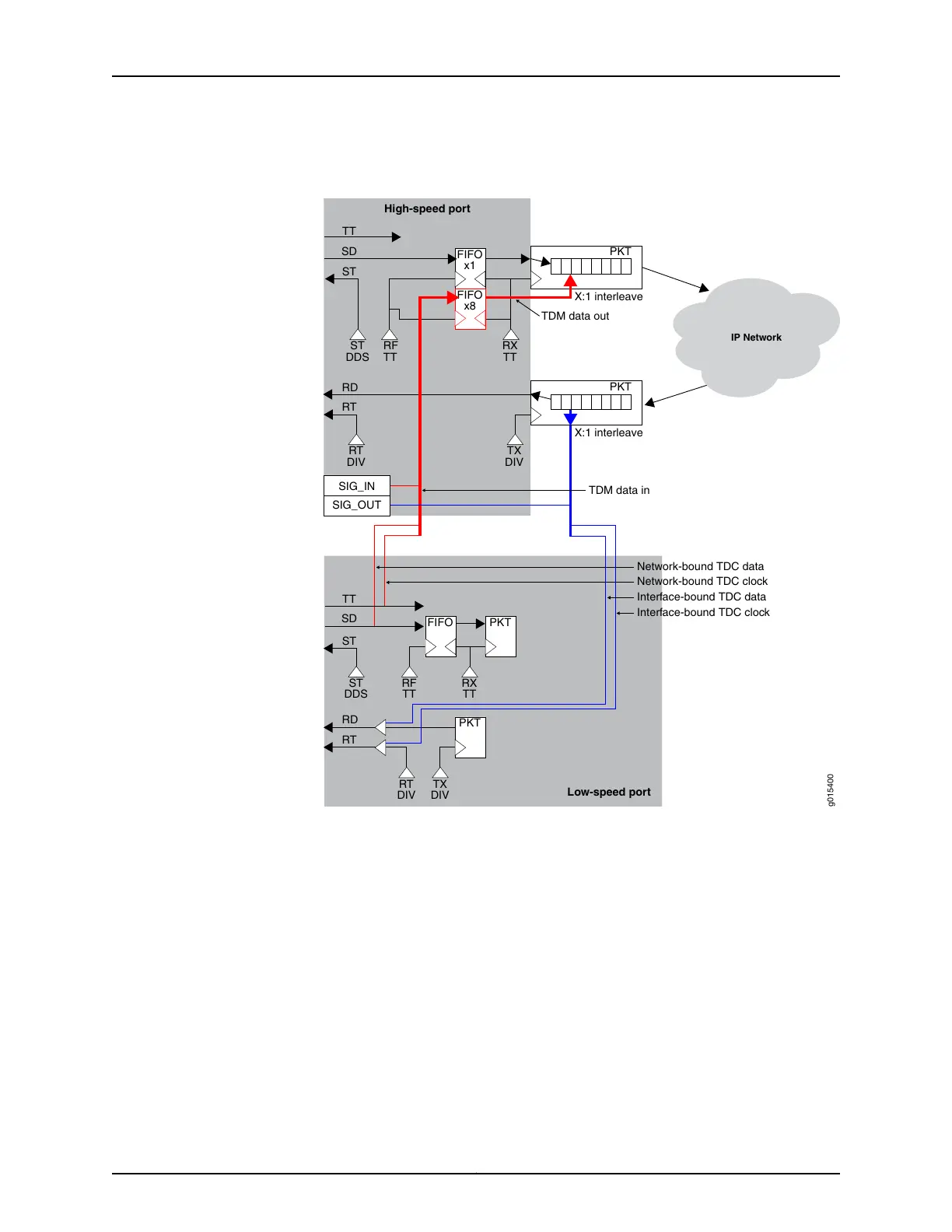
Figure 14: TDM/TDC High-Speed and Low-Speed Ports
g015400
Low-speed port
High-speed port
RT
RD
SD
TT
FIFO
x1
PKT
RX
TT
ST
RT
RD
SD
TT
RF
TT
ST
DDS
X:1 interleave
X:1 interleave
TDM data in
TDM data out
Network-bound TDC data
Network-bound TDC clock
Interface-bound TDC data
Interface-bound TDC clock
IP Network
TX
DIV
RT
DIV
PKT
SIG_IN
SIG_OUT
FIFO
x8
ST
ST
DDS
PKT
PKT
RT
DIV
TX
DIV
RF
TT
RX
TT
FIFO
As shown in the figure:
•
The red path shows the network-bound path for the low-speed TDC data and clock.
The low-speed port receives the clock and data signals from the user equipment, and
transmits it to the transmit data jitter FIFO on the high-speed port. Once out of the
FIFO, the CTP device interleaves the TDC data streams into a single packet flow for
the TDM/TDC bundle.
•
The blue path shows the interface-bound path for the TDC data and clock. The
low-speed port transmits the interface-bound clock and data from the TDM/TDC
bundle to the user equipment.
Related
Documentation
• Configuring Bundle Pairs for TDM/TDC Operation (CTP Menu) on page 64
• Configuring Bundle Pairs for TDM/TDC Operation (CTPView) on page 62
21Copyright © 2018, Juniper Networks, Inc.
Chapter 1: Overview of CTP Bundles