•
Handles arbitration among the CFMs
•
Handles switching among multiple SPCs if present
•
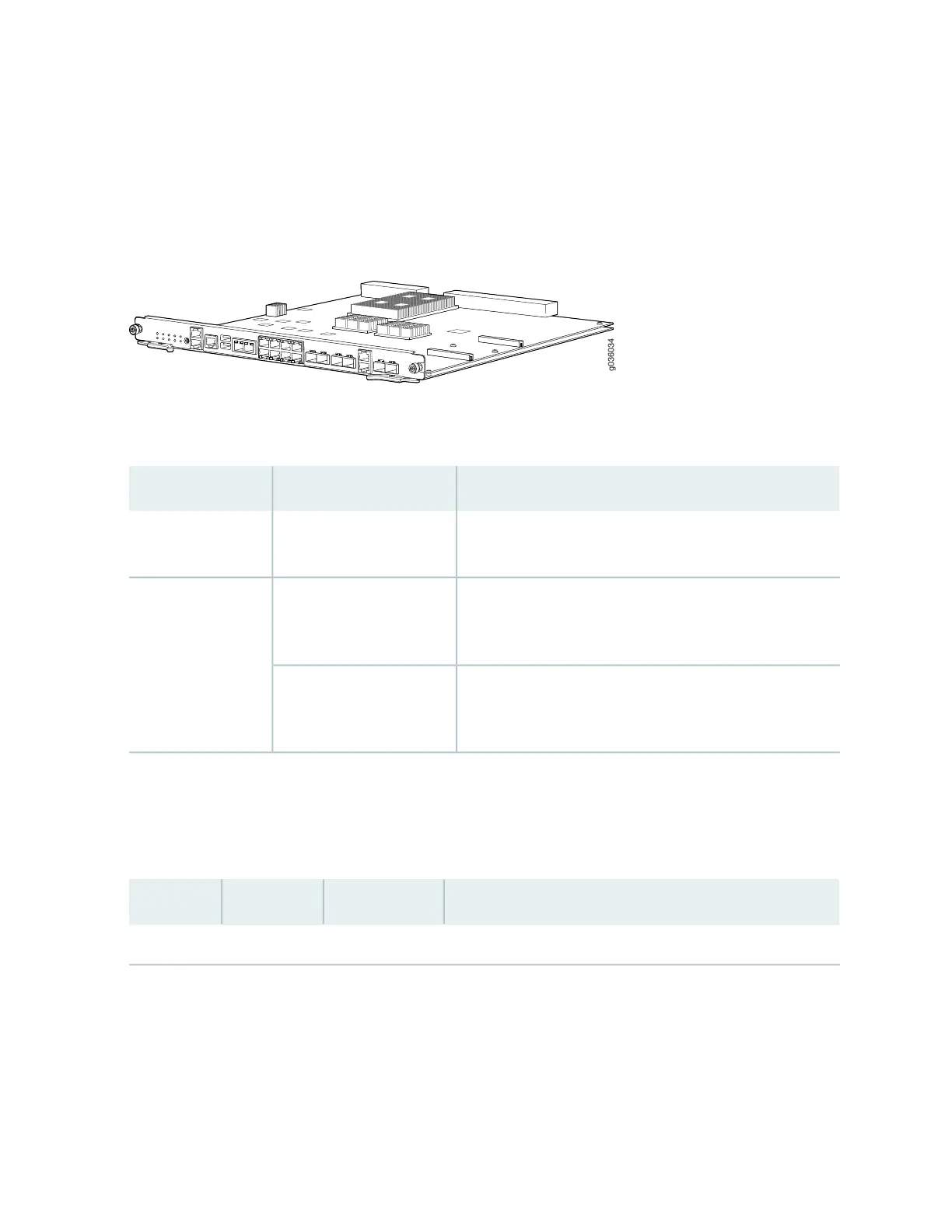
Provides service ports, system LEDs, and operational buttons on the front panel
Figure 2: Switch Fabric Board
Table 5 on page 8 describes the behavior of the Power button near the left end of the SFB front panel.
Table 5: Power Button Behavior
ResultActionCondition
Powers the services gateway on. The PWR LED blinks to
show you that the Routing Engine is initializing.
Short push (3 to 5 seconds)Services gateway
powered off
Initiates a graceful shutdown that preserves the services
gateway state information. The PWR LED blinks to show you
that the services gateway is shutting down.
Short push (3 to 5 seconds)Services gateway
powered on
Initiates an immediate shutdown. The services gateway state
information will be lost. Avoid using immediate shutdown
unless necessary.
Long push (15 seconds or
more)
Table 6 on page 8 describes the system behavior indicated by the various LEDs on the front panel of the
SFB. LEDs are listed based on their location on the services gateway, from left to right. Table 7 on page 12
describes the ports/connections available on the front panel of the SFB.
Table 6: Switch Fabric Board LED Indicators
Indicated BehaviorStatusColorLabel
Alarm (pair)
8
 Loading...


