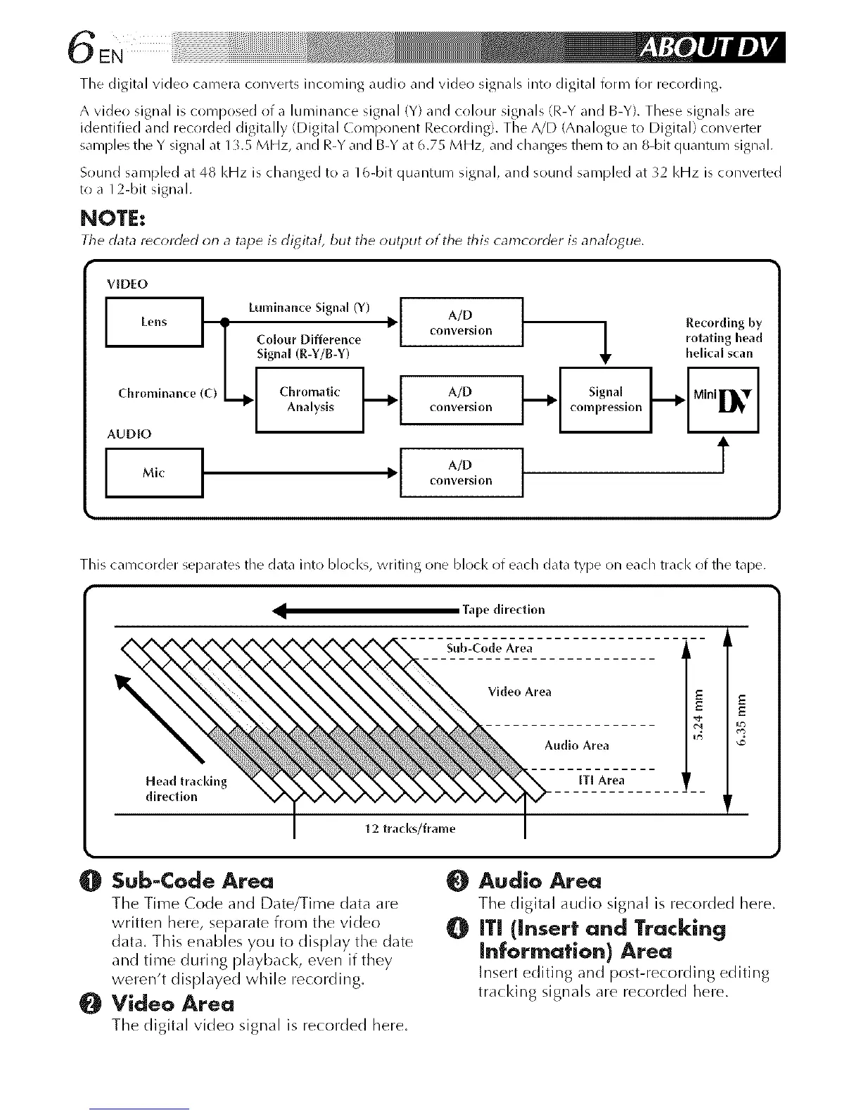
Tile digital video camera converts incoming audio and video signals into digital form for recording.
A video signal is composed of a luminance signal (Y) and colour signals (R-Y and B-Y). These signals are
identified and recorded digitally (Digital Conlponent Recording). The A/D (Analogue to Digital) converter
samples the Y signal at 1L5 MHz, and R-Y and B-Y at 6.75 MHz, and changes them to an 8-bit quantum signal.
Sound sampled at 48 kHz is changed to a 16-bit quantum signal, and sound sampled at 32 kHz is converted
to a 12-bit signal.
NOTE:
The data recorded on a tape is digital, but the output of the this camcorder is analogue.
VID[O
I L.,,,inan,e Signal (Y) . I I
Lens -- _ A/D
J IT Co,our Differen,e I ,onverslon
I
--I Ana,,s,sI'1 on ors,on
AUDIO ' --
Mic conversion
Signal
compression
Recording by
rotating head
helical scan
t
This camcorder separates the data into blocks, writing one blocl< of each data type on each track of the tape.
Tape direction
Sub-Code Area •
Vldeo Area
Z E
Audio Area
Head traddng Ill Area •
direction
12 trad(s/frame
Sub-Code Area
The Time Code and Date/Time data are
written here, separate from the video
data. This enables you to display the (late
and time during playback, even if they
weren't displayed while recording.
Video Area
The digital video signal is recorded here.
Audio Area
The digital audio signal is recorded here.
0 ITI (insert and Tracking
Information) Area
Insert editing and post-recording editing
tra(l<ing signals are recorded here.