KACO blueplanet 3.0 NX3 M2 KACO blueplanet 5.0 NX3 M2 KACO blueplanet 8.0 NX3 M2 KACO blueplanet 10.0 NX3 M2
KACO blueplanet 15.0 NX3 M2 KACO blueplanet 20.0 NX3 M2 Page 9
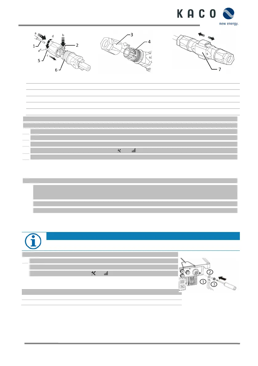
Fig. 13: Slide insert into sleeve
You have completed the assembly.
NOTE: Before proceeding with the isolation ensure that you do not cut any individual wires.
1 Insert isolated wires with twisted ends carefully up to the connection.
NOTE: Wire ends must be visible in the spring.
2 Close the spring so that the spring latches and slide insert into sleeve.
3 Secure and tighten the cover on the cable fitting [ W_15/ 1.8 Nm].
4 Join insert with contact plug.
» Making the electrical connection
Connecting the PV generator
DC plug connector has to be configured and PV generator checked to ensure there is no ground fault.
NOTE: Note the different current-carrying capacity of PV1
and PV2 depending on the power class.
See max. input current in the data sheet as well as in the complete manual.
1 Remove protective caps from the required DC connection plugs on the underside of the device.
2 Connect the DC plug connectors to the DC positive and DC negative connectors in pairs (see fig. 8.2).
» The device is connected to the PV generator.
1.7 Creating equipotential bonding
Depending on the local installation specifications, it may be necessary to earth the device with a second
ground connection. To this end, the threaded bolt on the underside of the device can be used.
The device has been installed on the mount.
1 Insert the earth conductor into a suitable M5 ring cable lug and crimp the contact.
2 Align the terminal lug with the grounding conductor on the screw.
3 Tighten it firmly into the housing [ P_2/ 2.5 Nm].
» The housing is included in the equipotential bonding
M5 screw (already pre-assembled)
Earthing ground conductor
Connecting
 Loading...