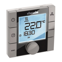
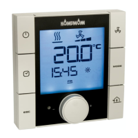
KaControl for Venkon
ASSEMBLY AND INSTALLATION INSTRUCTIONS
1.48
Venkon
34
DIP switch no. 2
In a 2-pipe system, changeover between heating and cooling is activated by the switching of digital
input DI2, with the following operating modes being executed according to the external contact:
Ext. contact open → Heating mode
Ext. contact closed → Cooling mode
Factory setting:
2-pipe system → DIP2 = ON
4-pipe system → DIP2 = OFF
Alternatively the changeover between heating and cooling in a 2-pipe system can also be activated
by a clip-on sensor. DIP switch no. 2 must be set to DIP2=OFF with this variation (see Section 10.3.5)
DIP switch no. 3
Operating functions can be locked using DIP switch no. 3. The following functions are possible after
setting DIP switch no. 3:
• Switch control on / off
• Set setpoint temperature
• Set fan stage
All other functions, such as the setting of timer programmes, specification of operating mode etc.,
are not activated.
Factory setting:
DIP3 = OFF
DIP switch no. 4
The convector configuration (2-pipe/ 4-pipe) is set by means of DIP switch no. 4.
Factory setting:
2-pipe system → DIP4 = OFF
4-pipe system → DIP4 = ON
DIP switch no. 5
DIP switch no. 5 must always be set to OFF!
Factory setting:
DIP5 = OFF
DIP switch no. 6
The internal sensor of the KaController or a clip-on sensor in the Venkon can be used to control the
room temperature.
Factory setting:
DIP6 = OFF → Room temperature control on a clip-on sensor in the Venkon
DIP6 = ON → Room temperature control on the internal sensor of the KaController
 Loading...