EasyManuals Logo

Kamstrup ULTRAFLOW 54 User Manual

Kamstrup ULTRAFLOW 54
77 pages
To Next Page IconTo Next Page
To Previous Page IconTo Previous Page
Page #19 background imageLoading...
Page #19 background image
TECHNICAL DESCRIPTION ULTRAFLOW
®
54 and 34
5512-385 GB/02.2014/Rev. H1
19
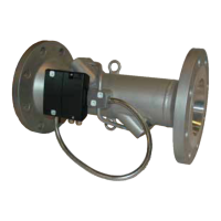
ULTRAFLOW
®
, DN65 to DN125
Figure 4
Flange EN 1092, PN25. Flange facing type B, raised face
Nom.
Diameter
Bolts
Approx.
weight
L M H2 B1 D H k Number
Thread
d
2
[
[[
[kg]
]]
]
DN65 300
170
89
<H/2
185
168
145
8 M16 18 13.2
DN80 300
170
89
<H/2
200
184
160
8 M16 18 16.8
DN80 350
170
89
<H/2
200
184
160
8 M16 18 18.6
DN100 360
210
89
<H/2
235
220
190
8 M20 22 21.7
DN100 400
210
89
<H/2
220
210
180
8 M16 18 22.8
DN125 350
212
89
<H/2
270
260
220
8 M24 28 28.2
Table 14

Table of Contents

Other manuals for Kamstrup ULTRAFLOW 54

Questions and Answers:

Question and Answer IconNeed help?

Do you have a question about the Kamstrup ULTRAFLOW 54 and is the answer not in the manual?

Kamstrup ULTRAFLOW 54 Specifications

General IconGeneral
BrandKamstrup
ModelULTRAFLOW 54
CategoryMeasuring Instruments
LanguageEnglish

Related product manuals