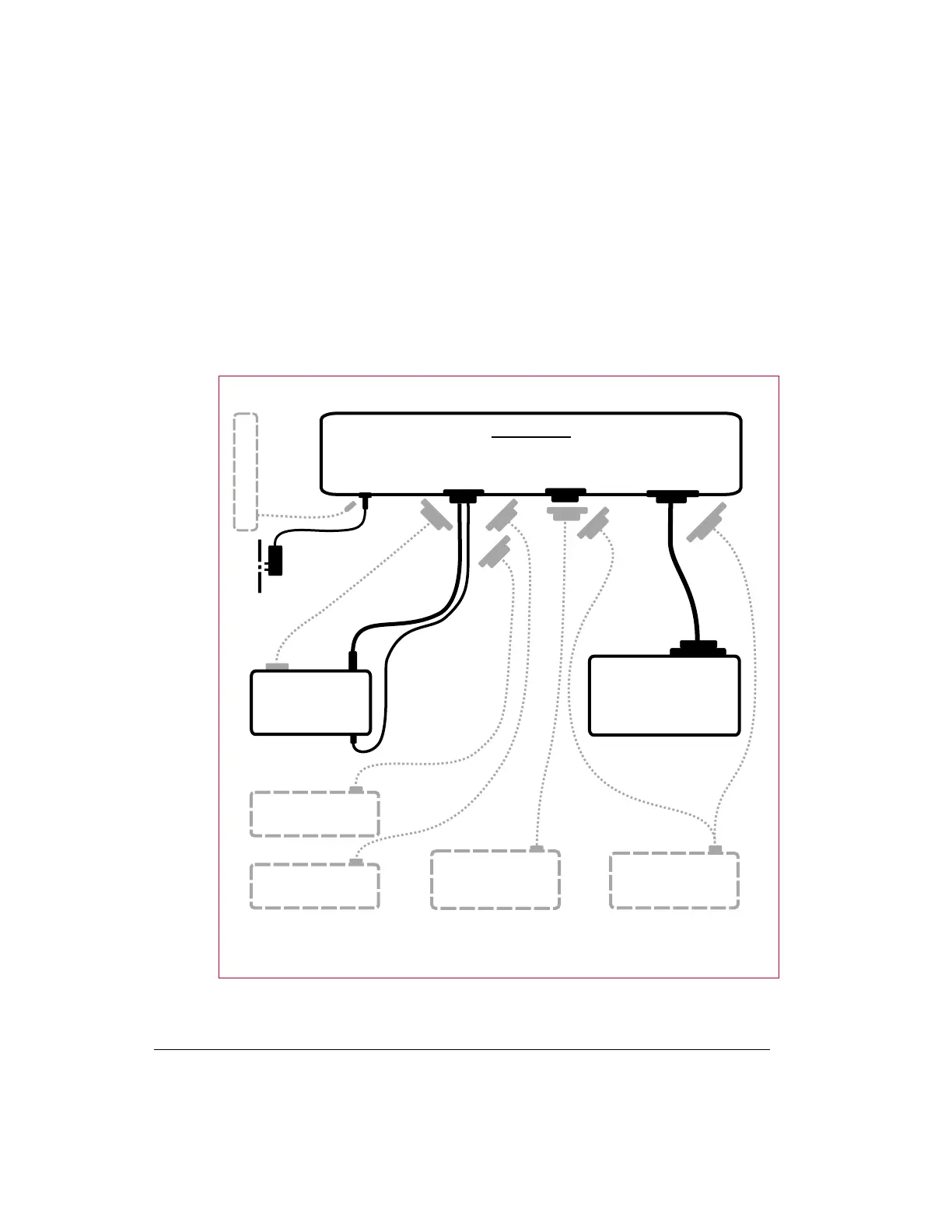
How the Parts of Your Station are Connected
The following diagram shows how the components of your KAM’98 multi-mode
digital radio station (including options beyond those covered in this chapter) will
be connected and the kinds of connectors that will be used.
Installing Your KAM’98 How the Parts of Your Station are
User’s Guide 40 KAM’98 v 8.3
Bench PowerSupply (12 Vdv)
KAM’98
(connections on back)
Po we r- c u b e :
Poweradaptor
(120 Va c /12 Vdc
with c a b le
a sse m b ly)
120 Va c
2.1 m m
powerjack
and stranded
2-c onduc tor
wire
Sh ie ld e d
RS-232
cable
Computer/GPS Port
DB-25 (fe m a le )
Po we r
2.1 mm
5-conductor
sh ie ld e d
cable
Mic
connector
Mo uld e d
mini-plug
cable
and jack
Da ta
ja c k
Microphone
Sp e a ke r ja c k
HF/VHF Ra d io
Ra d io Po r t
DB-9 (female)
AUX Po rt
DB-9 (female)
Computer
Ma rin e Ra d io
RTU (Re m o t e
TelemetryUnit)
© Cop yright 1998 by Ka ntronic s Co., Inc.
Ext e rn a l Mo d e m
Se ria l (C O M) Po rt
DB-9 o r DB-2 5 (m a le )
GPS Device