34
INSTALLATION AND CONNECTION
4 Installation and Connection
NOTICE
Destruction of the motor lter !
► Theconnectingcablesmustbexedwithadistanceof100mmin
order to ensure vibration resistance.
Information about the wiring
• Keeptheconnectionsbetweenthedriveconverterandoutputlterormotorchoke
as short as possible.
• Do not lay any other cables parallel to the motor cables.
• Onlyuseshieldedcablesbetweenoutputlter/motorchokeandmotor.
• For capacitors with double-hole cable lug, the inner hole must be used for the motor
connection and the outer hole for the capacitor connection.
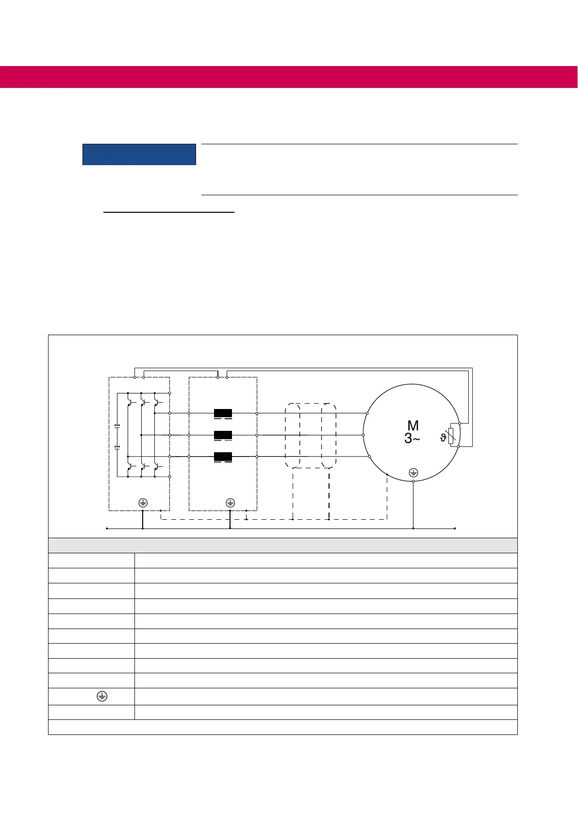
4.1 Schematic diagram with motor choke
① ② ③ ④
++
U
V
W
PE
PE
U
V
W
T1 T2 T1 T2
U1.1
V1.1
W1.1
U1.2
V1.2
W1.2
– –
Legend
①
Drive converter
②
Motor choke
③
Shielded motor cable
④
Motor
T1, T2 Connection temperature monitoring
U, V, W Output drive converter
++, - - Connection DC link
U1.1, V1.1, W1.1 Input motor choke
U1.2, V1.2, W1.2 Output motor choke
PE /
Protective earth connection
― ― ― Functional equipotential bonding via metal housing on galvanized mounting plate
Figure 10: Schematic diagram with motor choke
 Loading...