35
INSTALLATION AND CONNECTION
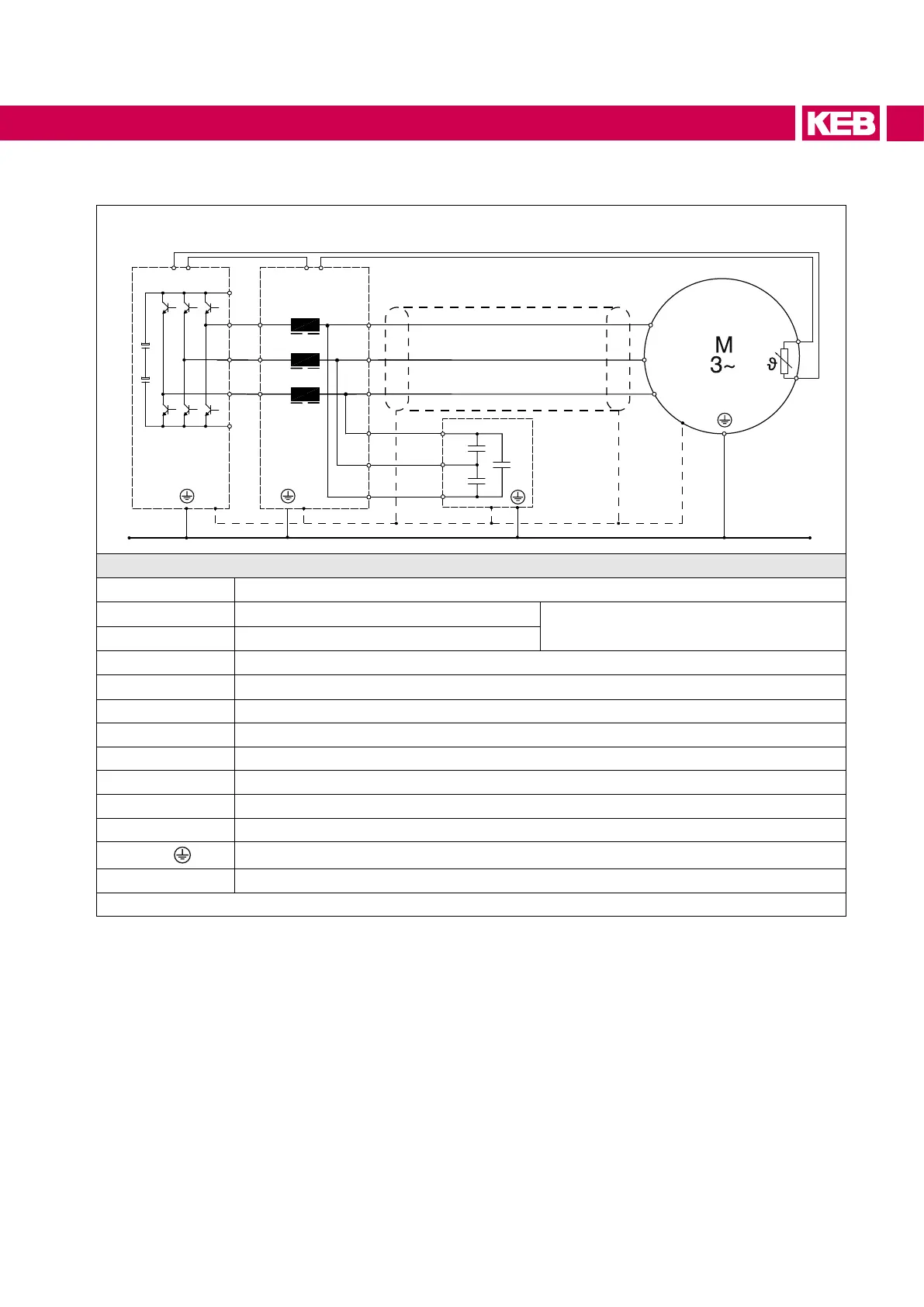
4.2 Schematic diagram with output lter
++
U
V
W
PE
PE
U
V
W
T1 T2 T1 T2
① ② ③
U1.1
V1.1
W1.1
U1.2
V1.2
W1.2
④
U1.3
V1.3
W1.3
⑤
– –
U1.2
V1.2
W1.2
Legend
①
Drive converter
②
Motor choke
Outputlter
③
Capacitor module
④
Shielded motor cable
⑤
Motor
T1, T2 Connection temperature monitoring
U, V, W Output drive converter
++, - - Output terminal DC link
U1.1, V1.1, W1.1 Input motor choke
U1.2, V1.2, W1.2 Output motor choke
U1.3, V1.3, W1.3 Connection capacitor
PE /
Protective earth connection
― ― ― Functional equipotential bonding via metal housing on galvanized mounting plate
Figure 11: Schematic diagram with output lter
 Loading...