31
MECHANICAL INSTALLATION
3.4 Mechanical installation
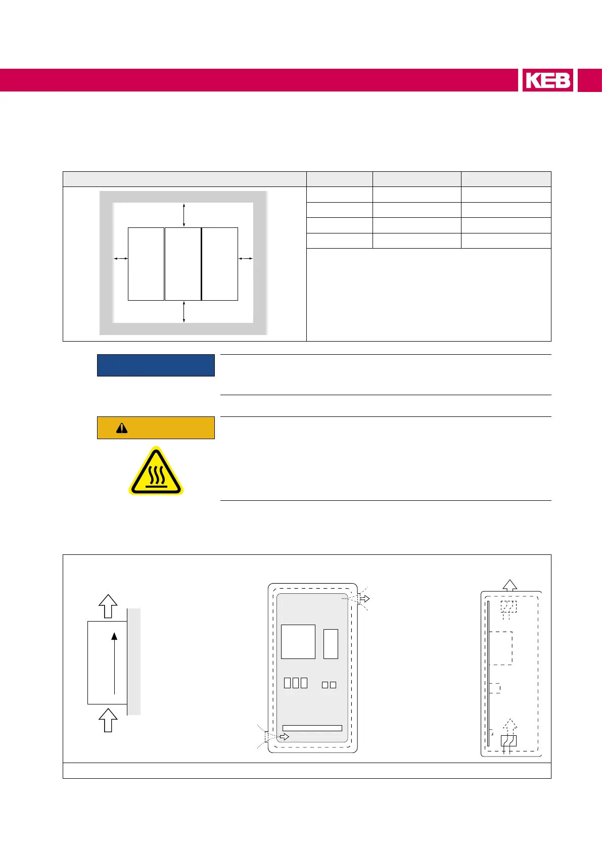
3.4.1 Control cabinet installation
Mounting distances Dimension Distance in mm Distance in inch
C
A
B
C
A 150 6
B
1)
100 4
C 30 1.2
X
2)
50 2
1) Minimum distance for cooling
2) Distance to preceding elements in the cabinet
door.
ATTENTION
Horizontal installation in the control cabinet must be done with special
care and the displacement between the units must be kept to a minimum.
CAUTION
Hot Surface
Heat sinks can reach temperatures, which can cause burns when touch-
ing. If in case of structural measures a direct contact cannot be avoided,
a warning notice "hot surface" must be mounted at the machine.
If construction-conditioned the control cabinet cannot be without indoor ventilation, ap-
propriate lters must avoid suction of foreign objects.
Direction of the air
ow
Front and side view of the coolant inlet
Coolant outlet
Coolant inlet
Figure 1: Control cabinet installation
 Loading...


